Technical Manual 5050 / MAN000539 Page 71/92
Epec Oy reserves all rights for improvements without prior notice
Epec Oy Postiosoite/Postal address Puhelin/Phone Fax Internet
Tiedekatu 6 PL/P.O.Box 194 +358-(0)20-7608 111 +358-(0)20-7608 110 www.epec.fi
FIN-60320 Seinäjoki FIN-60101 Seinäjoki, Finland
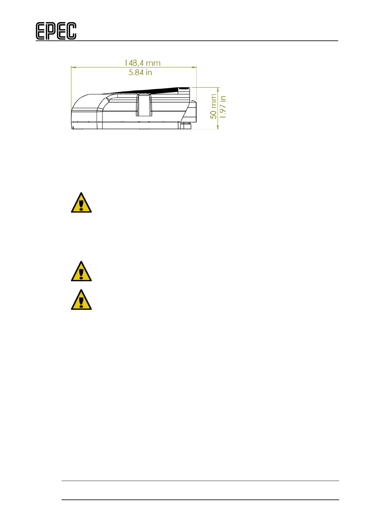
Unit dimensions from the side:
8.2 Mounting and Cleaning
Control unit mounting location should be planned so that the machine's
washing does not damage the unit.
A direct water jet towards the control units should be avoided, especially when
using high pressure. Also, the use of any such solvent that causes damage to
electronic devices should be avoided when handling the control units.
When cleaning the control unit, do not use highly alkaline / acidic substances,
too hot water, or too heavy mechanical abrasion.
In moist conditions, the module must be mounted and oriented so that the
connectors are not filled with water.
• The mounting is done with 3 pieces of M6 screws to DIN 912
• It is possible to use a spring washer under the screw head
• Mounting must be done on to a conductive metal base. The control unit's aluminum
housing must have a galvanic connection to the machine frame
• 3-point mounting allows mounting on a slightly uneven surface
• Reserve 10 cm installation space for the connector cables
• Mounting position must be horizontal or vertical to allow water, etc. flowing away from
connectors, see the figures below.