Technical Manual 5050 / MAN000539 Page 29/92
Epec Oy reserves all rights for improvements without prior notice
Epec Oy Postiosoite/Postal address Puhelin/Phone Fax Internet
Tiedekatu 6 PL/P.O.Box 194 +358-(0)20-7608 111 +358-(0)20-7608 110 www.epec.fi
FIN-60320 Seinäjoki FIN-60101 Seinäjoki, Finland
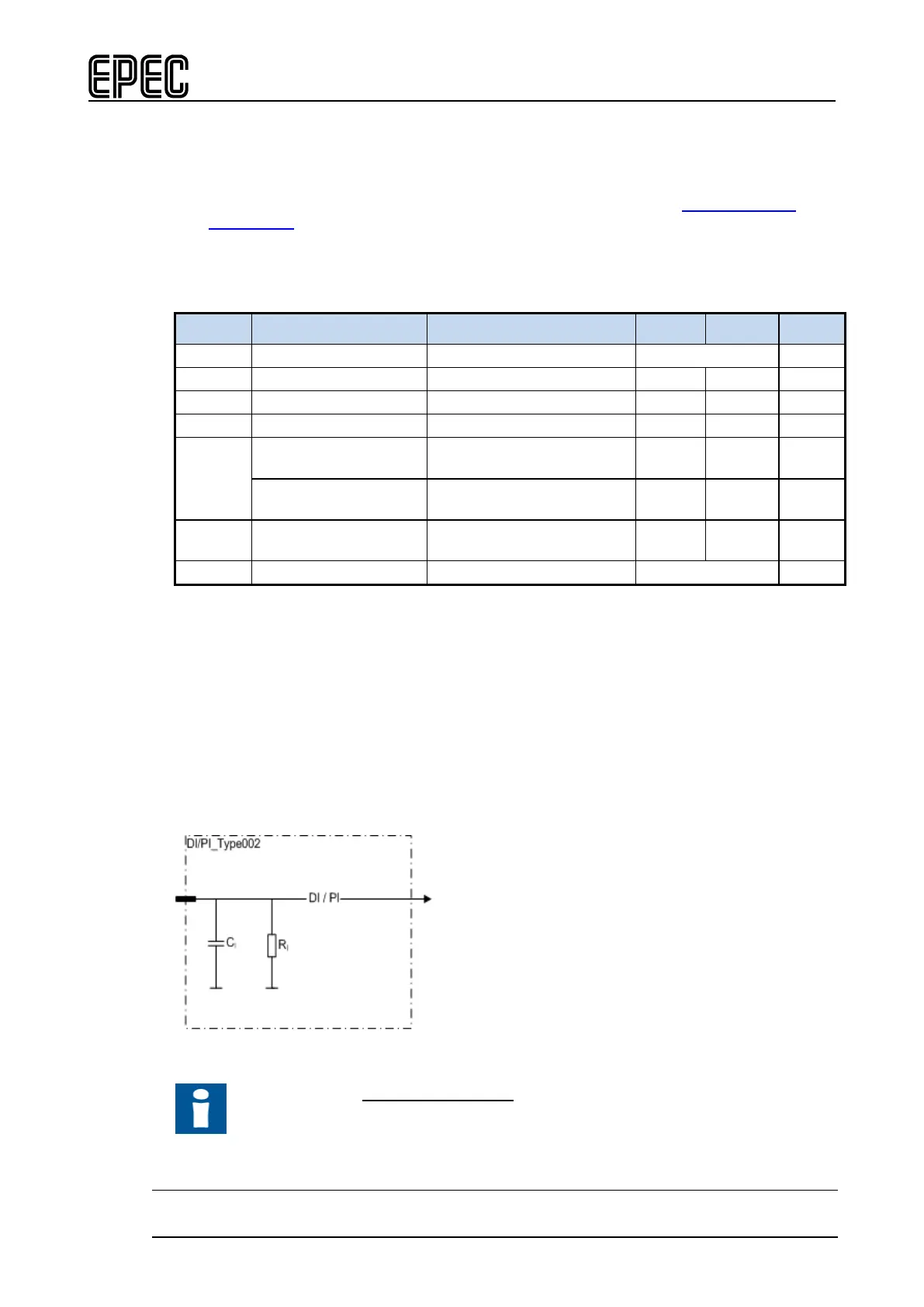
4.4.2 DI/PI_Type002
• This type of pin is a ground referenced input (DI) including a pulse counting (PI) feature.
• Pulse inputs can be used as a 1 or 2 channel pulse counter and they have a reset
possibility. Possible software channels and pairs are listed in section
SW channels for
Pulse Inputs.
• This type of pin has no configurable features
Electrical characteristics
Symbol Parameter Conditions Min Max Units
f
I
Input Frequency
tC= 4ms (Note 2,3,4,7) 250 Hz
Input Frequency
(Note 5,8) 5 20000 Hz
t
I
Input Pulse Width
(Note 5) 0,025 250 ms
Note 1: Exceeding the max values might cause damage to input.
Note 2: These parameters depend on software cycle time.
Note 3: Applies to inputs used as normal digital input. Violating this rating may lead to
application program not noticing all input state transitions.
Note 4: Pulse width must be greater that the software cycle time. For example with 50/50 pulse
ratio, the pulse frequency is 1 / (2*pulse width)
Note 5: Violating this rating may lead to system not recognizing all input state transitions.
Note 6: Overload conditions.
Note 7: tC denotes software cycle time.
Note 8: Max value can be reached by 2-98% pulse ration.
Functional block diagram
Other Information
Refer to section Connection Examples to see examples of how to connect external
actuators or sensors when using this type of pin.