Do you have a question about the epro MMS 6000 and is the answer not in the manual?
Configures a new monitor by selecting parameters like monitor type and operation mode.
Selects a predefined monitor configuration for specific applications.
Opens a dialog with property pages for setting device parameters.
Displays general data valid for the actual monitor type.
Configures device parameters including limit increase and suppression.
Configures individual channel parameters like sensor type and measuring range.
Sets parameters for data acquisition, including cut-off frequencies and control modes.
Configures parameters for output channels, especially for combined modes.
Displays the shaft speed in RPM, based on key pulses.
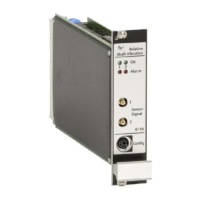
Shows the status of channel clear and alarm LEDs on the monitor.
Displays calculated characteristical values, often in bar diagrams.
Displays signal over time, FFT amplitude, and FFT phase data.
Performs and displays order analysis results if the diagnosis system is enabled.
Displays stored run-up and run-down data, including speed and amplitude.
Indicates module status, reasons for errors, and alarm functions.
Displays operational data like serial number, software version, and configuration.
Shows static parts of input signals, including operating range limits.
Describes the hardware functions of the amplifier and signal conditioning.
Details differential signal inputs and sensor supply outputs for the monitor.
Explains signal conditioning based on configuration and calculation methods.
Describes the analog and digital outputs for characteristic values.
Details analog outputs for characteristic values (0-20mA or 4-20mA).
Describes voltage outputs (0-+10V) for shaft vibration signals.
Provides dynamic part of the measuring signal for frequency analysis.
Describes scaled DC outputs proportional to sensor-target distance.
Describes voltage inputs and the key input for measurement control.
Describes voltage inputs for characteristical values, used with EO outputs.
Details the key input for reference pulses controlling measurement procedures.
Explains alarm channels, limit settings, and supervision functions.
Sets up alarm channels with pre-alarm (ALERT) and main alarm (DANGER).
Allows increasing limit values using a multiplier and the Factor X input.
Shows alarm states via red LEDs on the monitor front.
Describes the four open-collector alarm outputs and their functions.
Explains the function to latch alarms until they are manually reset.
Defines alarm output mode (open/closed circuit) via digital inputs.
Disables alarm LEDs and outputs during specific fault or delay conditions.
Explains how external signals can deactivate alarms and LEDs.
Allows adjustment of the delay time before an alarm is triggered.
Checks monitor and measuring chain functionality, indicating faults.
Checks input voltage against sensor operating range limits.
Detects if the dynamic signal amplitude exceeds the measuring range.
Indicates channel status with steady green or flashing LEDs.
Describes the two open-collector Channel Clear outputs.
Explains signalization of module supervision via LEDs and outputs.
Details monitor dimensions, mounting, power supply, and cable connection.
Explains the need for initial configuration with predefined parameters.
Discusses maintenance, contact for problems, and repair procedures.
Details signal inputs, sensor outputs, dynamic outputs, and calculation methods.
Details monitoring functions, thresholds, system voltages, and status visualization.
Describes limit setting, response delay, alarm blocking, and visualization.
Details RS 232 and RS 485 interfaces for connection and communication.
Explains system supply voltages, power consumption, and sensor supply.
Lists application class, temperature, humidity, vibration, and acceleration specs.
Details printed circuit board format, width, connectors, and weight.