MMS6110Directionforuse
Functiondescription Page34
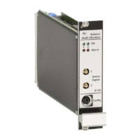
4.4.3 Alarmvisualization
TworedLEDsonthefrontplateindicatethealarmstateoftherelevantchannel.Main
alarms(DANGER)areindicatedbyasteadyredlight,incaseofpre-alarms(ALERT)the
LEDsareflashing–provided,neitherthealarmblockingfunctionhasbeenactivatednor
digitalinput"externalblocking"isset.
4.4.4 Alarmoutputs
Thefouralarmoutputsareopencollectoroutputsandaregalvanicallyisolatedfromeach
otherandfromtheremainingcircuitsofthemodule.Thustheswitchingfunctionoftheoutput
isonlygivenwithanexternalsupply.
Channel1: MainalarmD1-C,D1-E(d26,d28), Pre-alarmA1-C,A1-E(b26,b28)
Channel2: MainalarmD2-C,D2-E(d30,d32), Pre-alarmA2-C,A2-E(b30,b32)
Ifseveralalarmoutputsaretobeconnectedinseries,(closed-circuitmode),ithastobe
takenintoaccountthateachoftheoutputstakesavoltagedropofmax.1.5V.Forthisrea-
son,notmorethanfouroptocoupleroutputs(C-E)shouldbeconnectedinseries,whendriv-
ingaREL020with24Vrelaysupply.WhenusinganREL010,upto8C-Eoutputsandwith
theREL054upto12C-E-outputsmaybeconnectedinseries.
4.4.5 Alarmlatching
FunctionAlarmlatchingmaybeactivatedonpropertysheetOutputchannel.Ifwith
thisfunctionanalarmisgenerated,itwillbelatchedandonlyberesetifthealarmcondition
is no longer true andif in menu Extras > commands command Reset latch chan-
nel1resp.channel2isgiven.
Withoutlatchingfunctionthealarmwillberesetassoonasthemeasuringvaluefallsbelow
theupperlimit(minushysteresis)orexceedsthelowerlimit(plushysteresis).
4.4.6 Switchoveropen-/closed-circuitmodeSC-A,SC-D
ThesignalstatesatthedigitalinputsSC-A(d24)forALERTalarmsandSC-D(z24)forthe
DANGERalarmsdefinethealarmoutputoperatingmode.
• IncasetheSC-inputisopenorHIGH(+24V),therelevantalarmoutputsoperateinthe
opencircuitmode,i.e.atactivatedalarmsthetransistor'scollector-emitterlineiscon-
ductingandanexternalconnectedrelayactivated(seefig.4,connectiondiagram).
• In case the SC- input is Low (0 V), the relevant alarm outputs operate in the closed-
circuitmode,i.e.atactivatedalarmsthetransistor'scollector-emitterlineisopen,thus
anexternalconnectedrelaywillbedeactivated(seefig.4,connectiondiagram).
Note:Whenthemoduleoperatesintheclosedcircuitmode,analarmwillbetrig
geredifthesupplyvoltagefailsorifthecardisremovedfromtherack.
Inthefollowingchaptersthereistalkaboutthedefaultstate(=noalarm)ofthealarmout-
puts.Defaultstatemeansanopencollector-emitterline(relaynotactivated)fortheopencir-
cuitmodeandaconductingtransistoroutput(relayactivated)fortheclosedcircuitmode.
Note:
ModulesoftypeMMS6110Caredeliveredfromthefactorywiththealarmoutputsfixed
totheclosed-circuitmode.Alarmoutputsofthesemodulescannotbeoperatedinthe
opencircuitmode.