Maintenance 5. Arm #1
108 G3 Rev.14
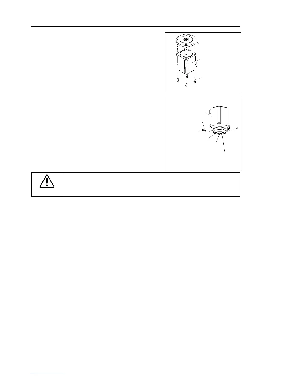
Joint #1 motor
Installation
Mount the motor flange on the Joint #1
waveform generator and motor flange.
Mount the waveform generator on
Be sure to fit the end face of the waveform
generator to the end face of the motor
face of the motor shaft until the screw
screw hole to prevent damage
to the motor shaft. Then, tighten
End face of the waveform generator
End face of the motor shaft
See the figures above for the orientation of the waveform generator. Be sure to
install the waveform generator properly. Improper
installation of the waveform
generator will result in improper function of the Manipulator.
Mount the motor unit to the Joint #1 flange.
oil seal (soft metal) hole to the mounting hole.
face the connector plate side.
If it is difficult to mount the motor, push it
while moving Arm #1 slowly by hand.
Mount the Joint #1 flange to the base.
Mounting positions of the Joint #1 flange and base are determined by the positioning
pin.
connectors.
Connectors: X110, X10, XB10
Mount the connector sub plate.
For the details, refer to Maintenance: 3.5 Connector Sub Plate.
Mount the connector plate.
For details, refer to Maintenance: 3.4 Connector Plate.
Mount the heatsink plate.
For details, refer to Maintenance: 3.7 Heatsink Plate.
Perform the calibration of Joint #1.
For details refer to Maintenance: 14. Calibration.

 Loading...


