EasyManuals Logo

Epson G3 Series User Manual

Epson G3 Series
200 pages
To Next Page IconTo Next Page
To Previous Page IconTo Previous Page
Page #76 background imageLoading...
Page #76 background image
Setup & Operation 5. Motion Range
64 G3 Rev.14
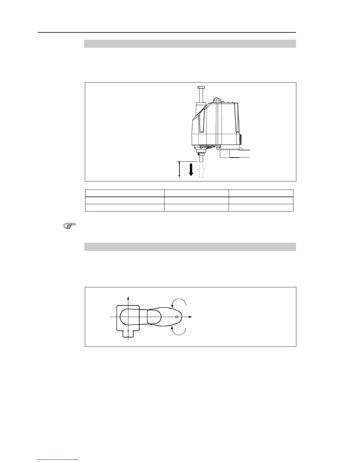
5.1.3 Max. Pulse Range of Joint #3
The 0 (zero) pulse position of Joint #3 is the position where the shaft is at its upper limit.
The pulse value is always negative because Joint #3 always moves lower than the 0 pulse
position.
Upper limit: 0 pulse
Model
Joint #3 Stroke
Lower Limit Pulse
G3-**1S*
150 mm
1706667
G3-**1C* (Cleanroom-model)
120 mm
1365334
For the Cleanroom-model (G3-**1C*), the motion range set with the Joint #3 mechanical
stop cannot be changed.
5.1.4 Max. Pulse Range of Joint #4
The 0 (zero) pulse position of Joint #4 is the position where the flat near the end of the
shaft faces toward the end of Arm #2. With the 0 pulse as a starting point, the
counterclockwise pulse value is defined as the positive (+) and the clockwise pulse value
is defined as the negative (-).
+Y
+X 0 pulse ± 1494221 pulse
Clockwise (-value)
Counterclockwise (
+value)
NOTE

Table of Contents

Questions and Answers:

Question and Answer IconNeed help?

Do you have a question about the Epson G3 Series and is the answer not in the manual?

Epson G3 Series Specifications

General IconGeneral
BrandEpson
ModelG3 Series
CategoryRobotics
LanguageEnglish

Related product manuals