Setup & Operation 3. Environments and Installation
38 G3 Rev.14
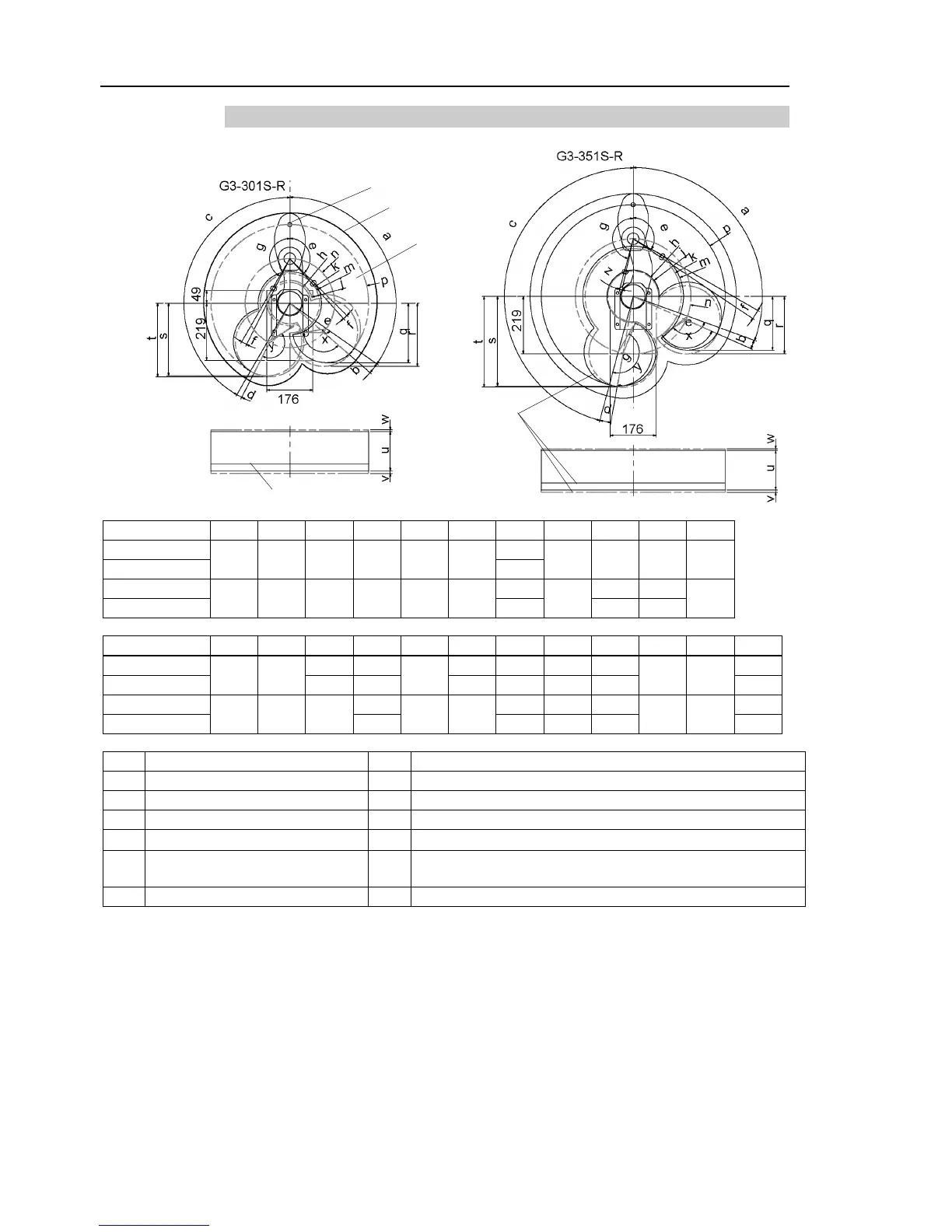
3.3.3 Table Top Mounting – Right-Curved Arm
Area limited
by mechanical stop
125° 6° 150° 3° 135° 3.3°
110° 4° 165° 5° 120° 3.8°
Joint #1 angle to hit mechanical stop (degree)
Joint #2 angle to hit mechanical stop (degree)
Joint #3 range to hit lower mechanical stop (mm)
Joint #3 range to hit upper mechanical stop (mm)
Motion range of Joint #1 (degree)
Range from center of axis to back end (mm)
e, g Motion range of Joint #2 (degree) r, t
Range from center of axis to back end after moved to
Joint #2 motion range + angle to hit mechanical stop (degree)

 Loading...


