EasyManuals Logo

Epson G3 Series User Manual

Epson G3 Series
200 pages
To Next Page IconTo Next Page
To Previous Page IconTo Previous Page
Page #122 background imageLoading...
Page #122 background image
Maintenance 5. Arm #1
110 G3 Rev.14
Joint #1
reduction gear
unit
Installation
(1)
A
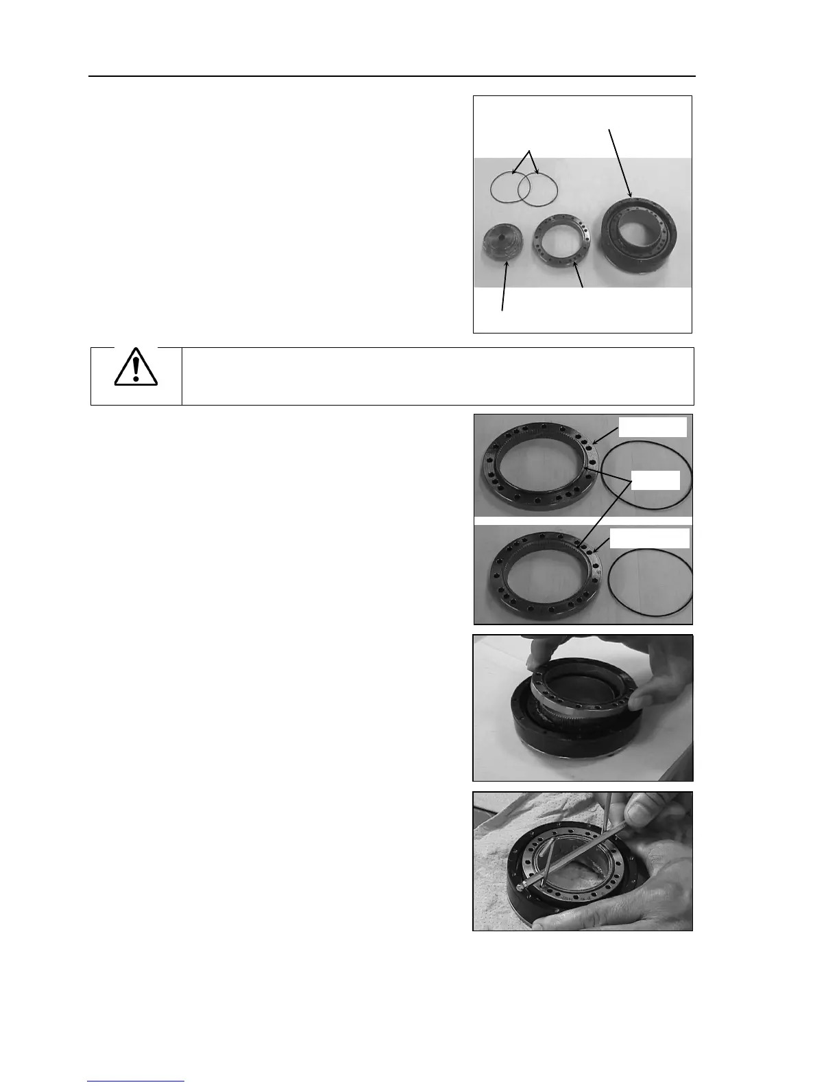
new reduction gear unit contains the
parts shown
in the picture on the right
when it
is unpacked.
The gear grooves of the flexspline,
circular spline
, and the bearings of the
waveform generator
have been greased.
Wipe off excess grease
from the
mounting
surface.
Fle
xspline and
Cross roller bearing unit
Circular spline
Waveform generator
O-ring
CAUTION
Never
adjust (loosen or tighten) the mounting bolts between the flexspline and
cross roller bearing unit.
If the mounting bolts are adjusted, the flexspline and
cross roller bearing unit must be
aligned by the maker of the reduction gear unit.
(2)
Fit the
O-rings into the grooves on both
side
s of the new circular spline.
Make
sure that the rings do not come out
of the grooves.
Convex side
Grooves
The other side
(3)
Face the convex side of the circular spline
down,
and then fit it into the flexspline.
(4)
M
atch the screw holes on the inner ring of
the cross roller bearing unit and the
through holes of the circular spline.

Table of Contents

Questions and Answers:

Question and Answer IconNeed help?

Do you have a question about the Epson G3 Series and is the answer not in the manual?

Epson G3 Series Specifications

General IconGeneral
BrandEpson
ModelG3 Series
CategoryRobotics
LanguageEnglish

Related product manuals