Maintenance 7. Arm #3
124 G3 Rev.14
Loosely secure the Joint #4 motor unit to
Arm
the motor unit can be moved by
hand, and it will not tilt when pulled.
If the unit is secured too loose or too tight,
the belt will not have the proper tension.
upper rotator part on the Arm #2 upper side with screws.
Rotate and move up/down the ball screw spline
Apply the proper tension to the U1 belt, and
secure the Joint #4 motor unit.
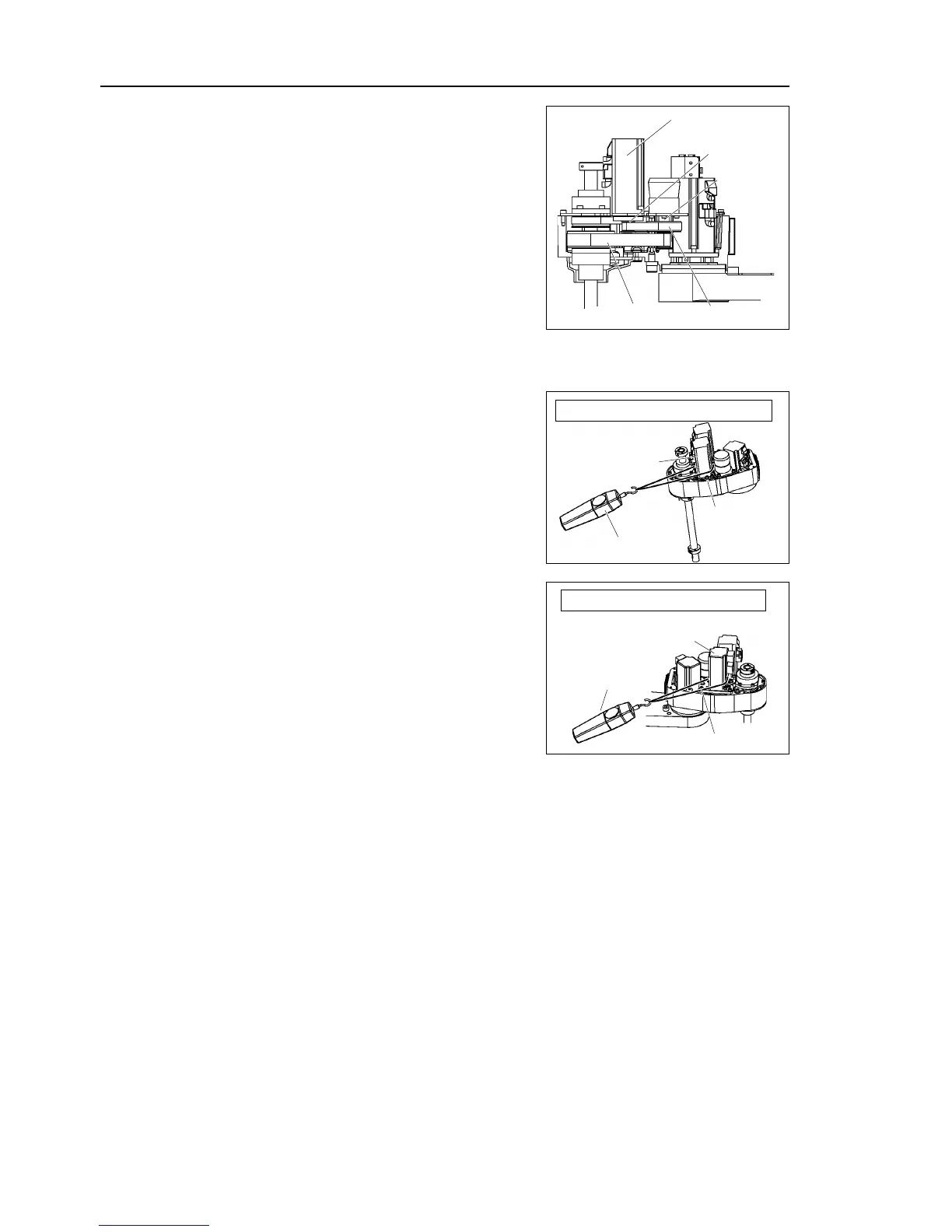
To do so, pass a suitable cord or string around
the Joint #4 motor unit near its mounting
plate. Then, pull the cord using a force
gauge or similar tool to apply the specified
tension shown in the figure on the right.
U1 belt tension = 74N (7.5 ± 0.5 kgf)
Apply the proper tension to the Z belt, and
secure the Joint #3 motor unit.
To do so, pass a suitable cord or string around
the Joint #3 motor unit near its mounting
plate. Then, pull the cord using a force
gauge or similar tool to apply the specified
tension shown in the figure on the right.
Z belt tension = 74N (7.5 ± 0.5 kgf)
Connectors: X231, X241, X31, X41
the cables in their original positions with the wire tie removed in the
Removal step (8).
Do not allow unnecessary strain
Connect the backup connectors for Joint #3 and #4 (X63, X64) to the battery board.
Bundle the backup cable with wire tie to prevent the cable connector to fall off by
mistake.
Mount the user plate and ground wire to Arm
Mount the battery board to the Arm
arm top cover and the arm bottom cover.
For details, refer to Maintenance: 3. Covers.
Perform the calibration of Joint #3 and #4.
For details, refer to Maintenance: 14. Calibration.

 Loading...


