Maintenance 7. Arm #3
130 G3 Rev.14
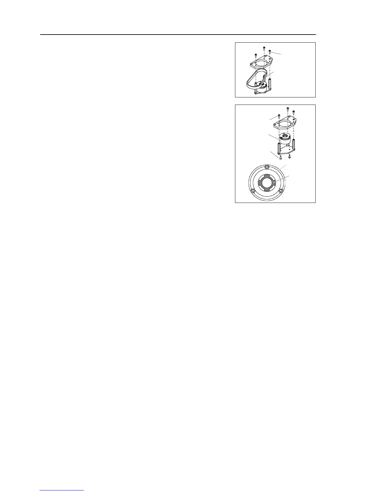
Mount the brake to the brake plate.
Mount the brake hub to the Joint #3 motor.
Mount the motor unit to the Z plate.
Align the position of the disk on the brake and the
hub.
When the brake disk is not aligned,
connector X32. Press the brake release switch
and release the brake to manually adjust the
position.
Mount the Joint #3 motor unit to Arm #2 so that the open side faces toward the end
of the arm.
For the brake hub mounting procedure, refer
7.1 Replacing Joint #3
Motor
- Joint #3 motor installation - Step (3) - (19).
top cover and the arm bottom cover.
For details, refer to Maintenance: 3. Covers.
the calibration of Joint #3.
For details, refer to Maintenance: 14. Calibration.

 Loading...


