EasyManuals Logo

Epson G3 Series User Manual

Epson G3 Series
200 pages
To Next Page IconTo Next Page
To Previous Page IconTo Previous Page
Page #155 background imageLoading...
Page #155 background image
Maintenance 8. Arm #4
G3 Rev.14 143
(6)
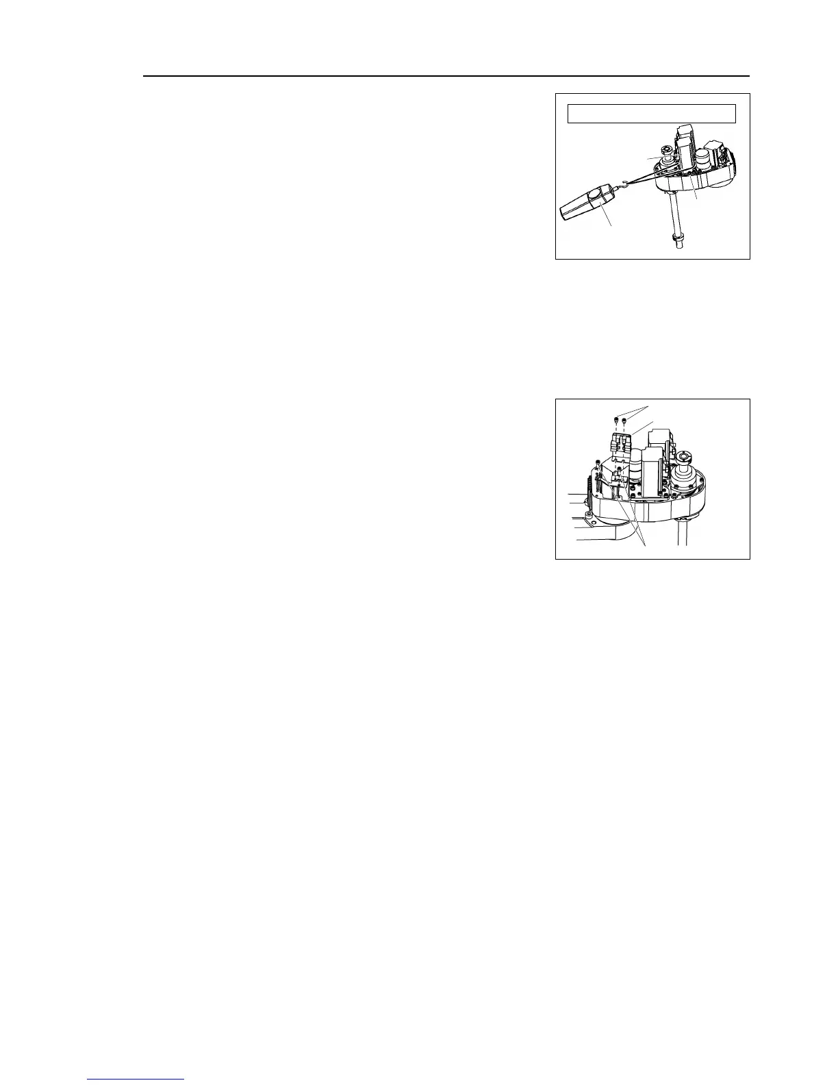
Apply the proper tension to the U1 belt, and
then secure the Joint #4 intermediate shaft
unit.
P
ass a suitable cord or string around the Joint #4
motor
unit near its mounting plate.
Then, pull the cord using
a force gauge or
similar tool to apply the
specified tension shown
in the figure on
the right.
3-M4×12
+ washer
U1 belt tension
= 7.5 ± 0.5
kgf
Force gauge
Joint #4
motor unit
(7)
Connect the connector.
Connector: X241, X41
(8)
Re
-bundle the cables in their original positions with a wire tie removed in step (9).
(9)
Connect the backup
connectors of Joint #4, X64 to the battery board.
Bundle the cables with wire tie to prevent the backup cable connectors from falling off
by mistake.
(10)
Mount the battery board to Arm #2.
2-M4×5
Battery board
2-M4×12
(11)
Mount the user plate and ground wire to Arm #2.
(12)
Install the arm
top cover and arm bottom cover.
For details, refer to Maintenance: 3. Covers.
(13)
Perform the calibration of Joint #4.
For details, refer to Maintenance: 14. Calibration.

Table of Contents

Questions and Answers:

Question and Answer IconNeed help?

Do you have a question about the Epson G3 Series and is the answer not in the manual?

Epson G3 Series Specifications

General IconGeneral
BrandEpson
ModelG3 Series
CategoryRobotics
LanguageEnglish

Related product manuals