Maintenance 10. Bellows
154 G3 Rev.14
bellows, move the shaft to its lower limit.
To attach the lower bellows, move the shaft to its
To move the shaft up/down, press and hold the brake release switch.
Be sure to keep enough space and prevent the
hitting any peripheral
equipment.
Joint #3. When the brake release switch is
pressed, the brake
for Joint #3 is released simultaneously.
shaft while the brake release switch is being pressed because the
shaft may be lowered by the weight of an end effector
Pass the shaft through the bellows
Secure the cover side of the bellows.
The bellows has two joints:
The larger joint must be attached to the cover side.
The smaller joint must be attached to the end face
side of the shaft.
Attach the mounting part of the bellows
cylindrical part of the cover.
Then, secure them with clamp bands.
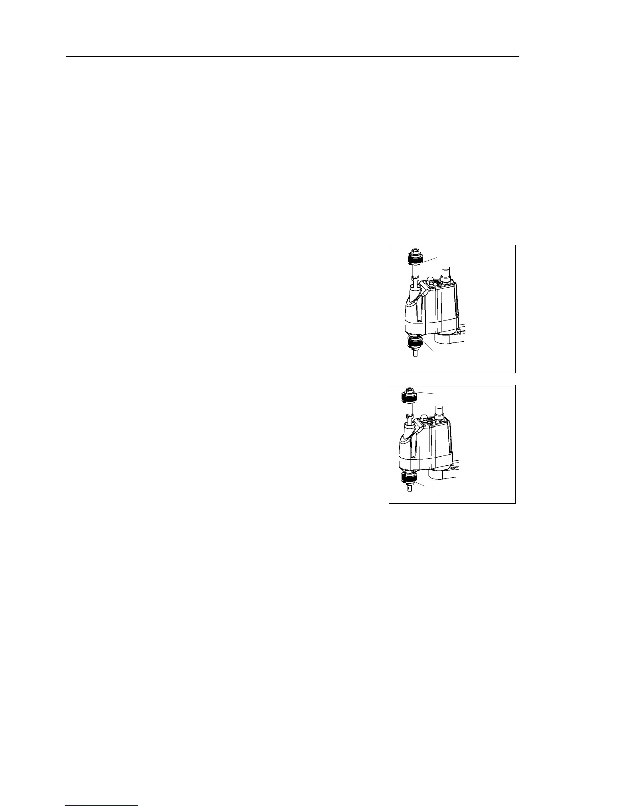
Bottom bellows
cover side
Secure the end face side of the bellows to the shaft.
over the bearing case (black) on the end face of
the bellows mounting part.
Then, secure them with clamp bands.
Bottom bellows
Shaft edge
After completing the attachment of the bellows, move the shaft up/down by hand
several times
ake sure that the bellows can expand and
contract smoothly without any excessive force.
Controller and peripheral equipment.
onnect the wires and tubes to the end effector.

 Loading...


