EasyManuals Logo

Epson G3 Series User Manual

Epson G3 Series
200 pages
To Next Page IconTo Next Page
To Previous Page IconTo Previous Page
Page #171 background imageLoading...
Page #171 background image
Maintenance 11. Ball Screw Spline Unit
G3 Rev.14 159
(7)
Remove
the battery board from Arm #2.
2-M4×5
Battery board
2-M4×12
(8)
Remove the user plate and grounding wire from Arm #2.
(9)
Disconnect the following connectors.
Connectors X231, X31X341X41 (Hold the claw to remove.)
Connector X32
Connector X63, X64 (Backup cable connector for Joint #3, #4)
(10)
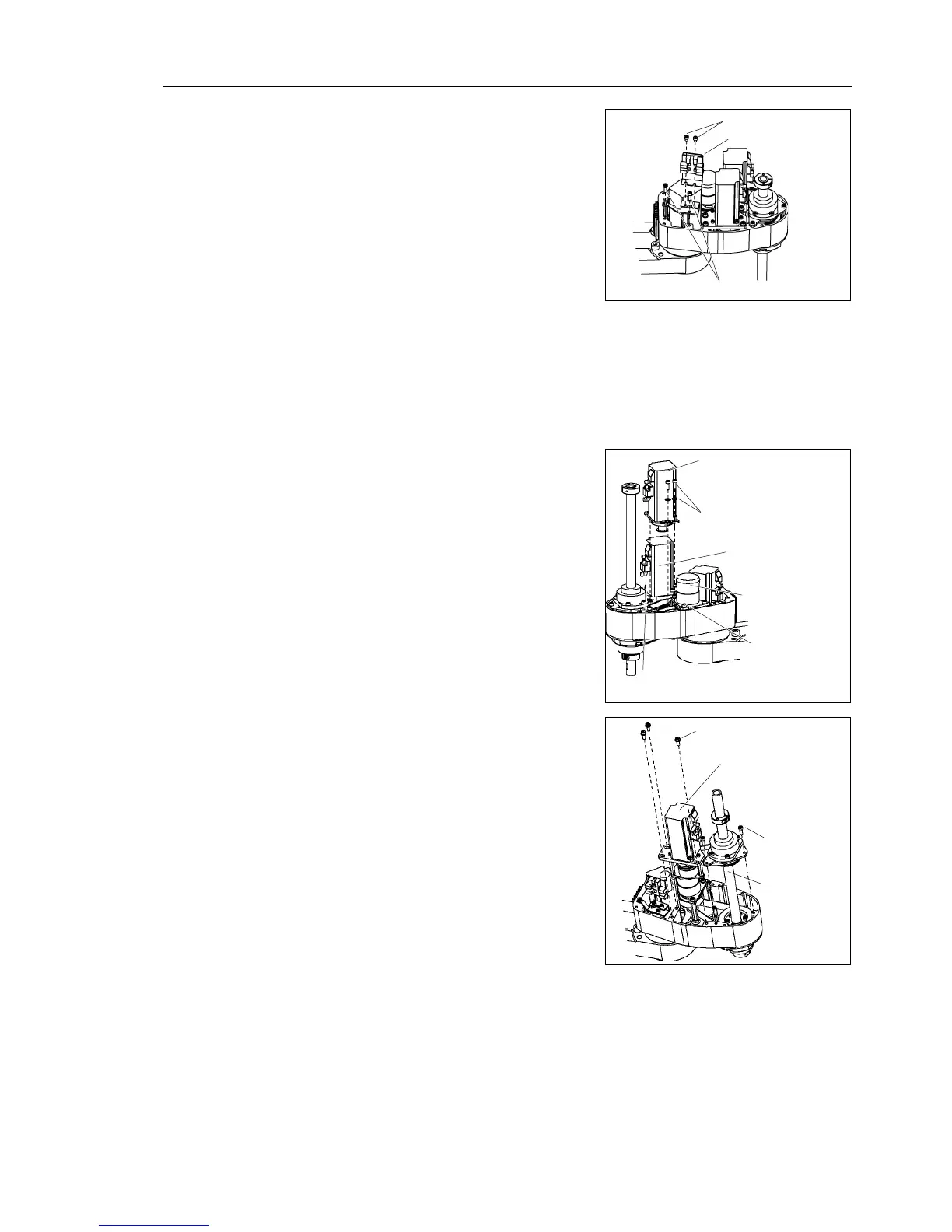
Remove the motor unit by pulling it up.
Remove the bolts securing the Joint #4
motor unit.
3-M4×12 + washer
Joint #4
motor unit
3-M4×12 + washer
Joint #2
motor unit
Joint #4
intermediate shaft
3-M4
×12
+ washer
(11)
Remove the
screws securing the ball screw
spline of Arm #3 surface.
(12)
Remove the screws securing the Joint #3
motor unit.
3-M4×12 + washer
Joint #3
motor unit
3-M4×12
Ball screw
spline unit
(13)
Hold the rotator part of ball screw spline
and Joint #3 motor up together.
(14)
Hold the
Joint #3 motor up.
Remove the belt by passing though the
spline rotator part.

Table of Contents

Questions and Answers:

Question and Answer IconNeed help?

Do you have a question about the Epson G3 Series and is the answer not in the manual?

Epson G3 Series Specifications

General IconGeneral
BrandEpson
ModelG3 Series
CategoryRobotics
LanguageEnglish

Related product manuals