Maintenance 6. Joint #2
102 L
S20-B Rev.4
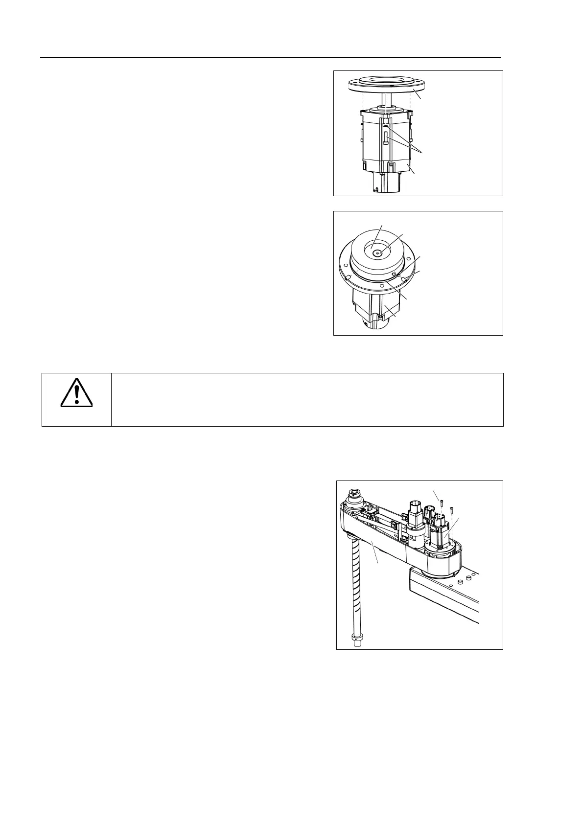
Joint #2 Motor
Installation
the motor flange on the Joint #2
4-M4×15
+ Plain Washer
Joint #2 Motor
Motor Flange
Mount the waveform generator on the Joint
#2 motor.
Be sure to
align the end face of the
generator to the end face of the
shaft.
screws vertically on
flat face of the motor shaft. Insert a
into the other set screw hole to
damage to the motor shaft.
2-M5×8
Set Screw
M5 Brass Bushing
End face of Waveform Generator
O-ring
Joint #2 Motor
End face of Motor shaft
CAUTION
■
See the figures above for the orientation of the
waveform generator. Be sure to
install the waveform generator properly.
Improper installation of the waveform
generator will result in improper function of the Manipulator.
Apply grease between the waveform generator and motor flange.
G
rease volume: 38 g (SK-1A)
ount the Joint #2 motor unit on the Arm #2.
To insert the motor, slowly move the Arm #2
by hand and push in.
Joint #2
Motor Unit
Arm #2
4-M5×20
and Duct Plate.
For details, refer to Maintenance: 3. Covers.
Connect the following connectors
.
Connectors: X221, X42

 Loading...


