Maintenance 6. Joint #2
106 L
S20-B Rev.4
eduction
ear Unit
new
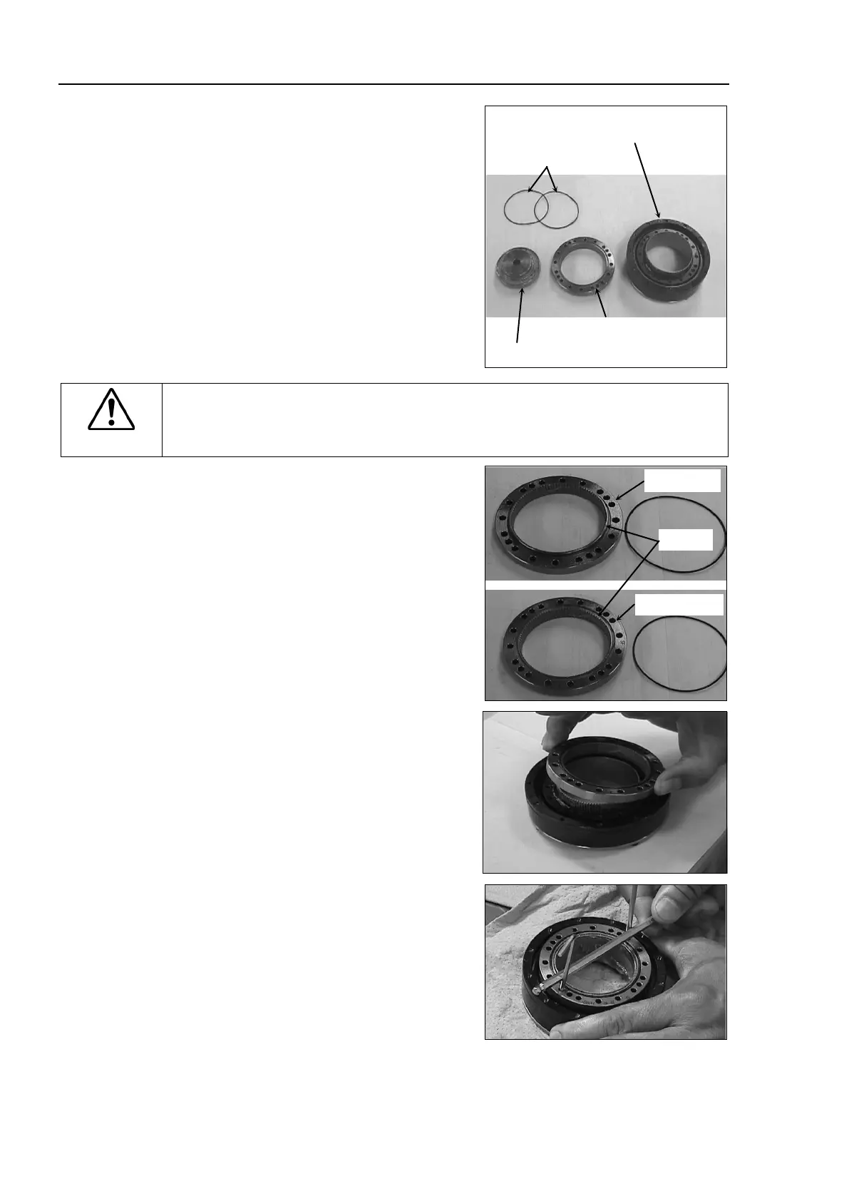
reduction gear unit contains the
parts shown
in the picture on the right
is unpacked.
he gear grooves of the flexspline, circular
, and the bearings of the waveform
have been greased. Wipe off
from the mounting surface.
Flexspline and
Cross roller bearing unit
C
AUTION
■
adjust (loosen or tighten) the mounting bolts between the flexspline and
cross roller bearing unit.
If the mounting bolts are adjusted, the flexspline and
cross roller bearing unit must be
aligned by the maker of the reduction gear unit.
O-rings into the grooves on both
s of the new circular spline.
sure that the rings do not come out
Face the convex side of the circular spline
down,
and then fit it into the flexspline.
If it is difficult to fit in, rotate the
circular
spline a little bit and change the position.
atch the screw holes on the inner ring of
the cross roller bearing unit and the
through holes of the circular spline.

 Loading...


