Maintenance 6. Joint #2
LS20-B Rev.4 107
the cross roller bearing to
.
4-M4×20
Tightening torque: 4.0 N·m (40.8 kgf·cm)
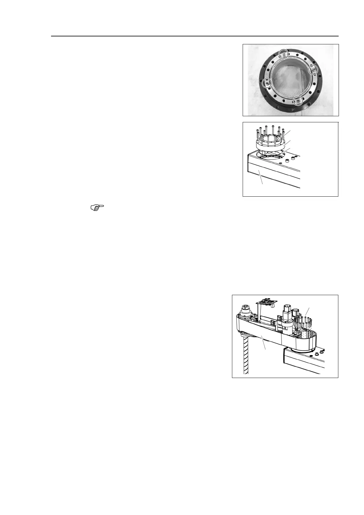
Set the O-ring removed in the removal step (6)
into the O-ring groove of the Arm #1.
Install the reduction gear unit on the Arm #1.
Hexagon socket head cap bolts: 12-M5×40
Tightening torque: 10.0 N⋅m (102 kgf⋅cm)
Arm #1
12-M5×40
Reduction Gear
Unit
O-ring
Loosely secure all bolts in a crisscross pattern so that the bolts will be secured evenly.
Then, using a torque wrench, tighten each bolt securely in a crisscross pattern at the
torque specified in the
above.
Apply grease between the motor flange an
d waveform generator and next inside the
Between the motor flange and waveform generator:
Grease volume: 38 g (SK-1A)
Inside the flexspline:
Grease volume: 90 g (SK-1A)
Set the attached O-ring into the O-ring
groove of the circular spline.
Secure the Arm #2 on the reduction gear
unit.
Mount and Joint #2 motor.
Follow the installation steps in Maintenance: 6.1 Replacing Joint #2 Motor.

 Loading...


