Maintenance 7. Joint #3
LS20-B Rev.4 121
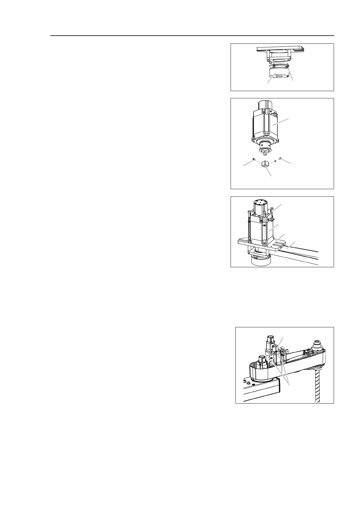
Mount the brake to the brake plate.
Mount the brake hub to the
pulley of the
Fix the brake hub while aligning it to the
end
Tighten one of the set screws
vertically on
the flat face of the motor shaft.
Insert a bushing into the other set screw
hole
to prevent damage to the motor shaft.
Joint #3
Motor
M3×4 Set Screw
+M3 Bushing
Brake hub
M3×4
Set Screw
Mount the Joint #3 motor to the motor
plate
while aligning the hub to the
brake disc.
Before aligning the hub, set the motor so
that
the pulley will be inside of the Z belt.
Joint #3 Motor
4-M4×15+
Plain washer
Motor Plate
Z Belt
When the brake disc is not aligned, manually adjust the position by following the
steps
1. Connect the connector BR3.
2. Press the brake release switch to release the brake.
3. Adjust the brake disc manually so that the hole is at the center.
Apply the proper tension to the Z belt, and
secure the Joint #3 motor unit.
For details, refer to the installation steps in
Maintenance 7.2 Replacing the Timing Belt.
Joint #3
Motor Unit
3-M5×20
+washer for
slotted hole
Mount the User Plate and the Duct Plate.
For details, refer to Maintenance 3. Covers.
connectors.
Connectors: X231, X43, BR3

 Loading...


