Maintenance 8. Joint #4
LS20-B Rev.4 137
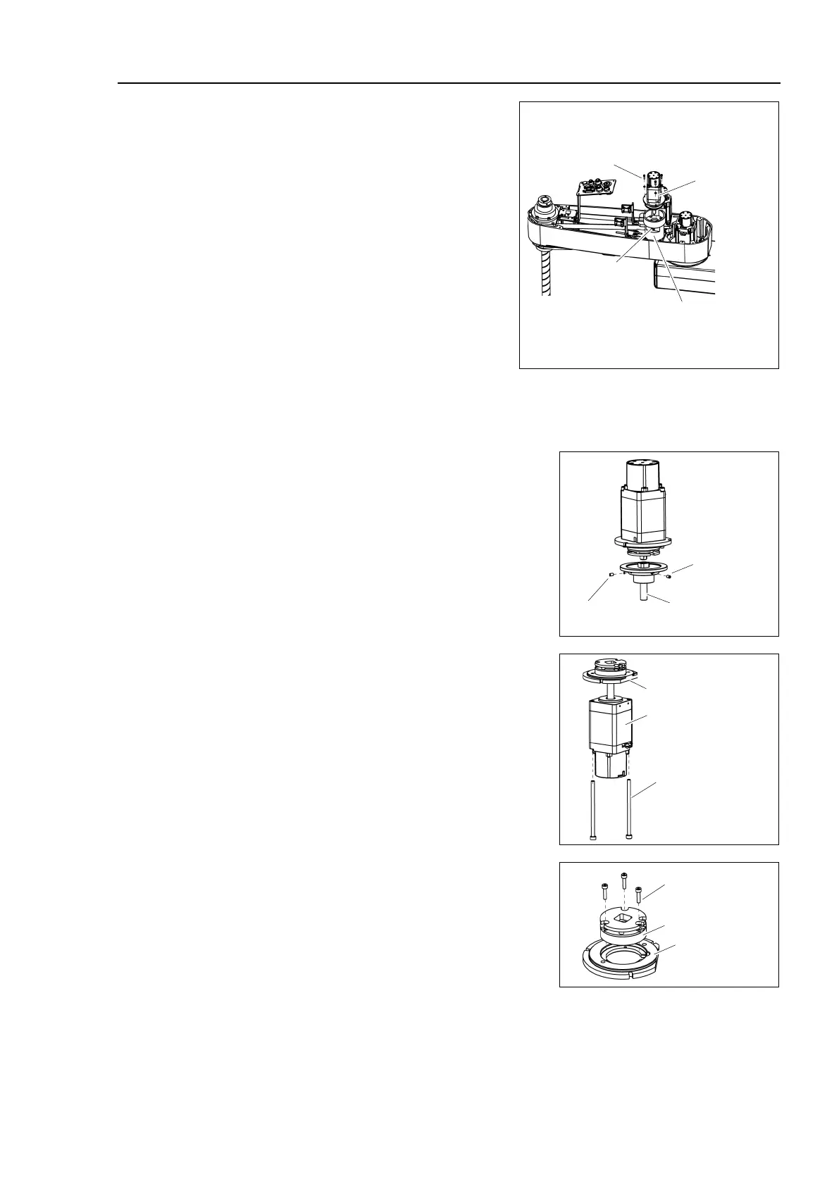
Remove the screws securing the Joint #4
motor
unit on the reduction gear unit.
Joint #4
Motor Unit
3-M3×12
+ plain washer
Hole for fixing the
extension shaft
Joint #4
Reduction gear unit
Remove the cover of the hole for fixing
the
extension shaft on the side of the
gear, and loosen the screws.
If the screw position does not match, turn
the motor
slightly and move until the
extension shaft can be
oint #4 motor unit from the
ount the cover of the hole for fixing the extension shaft on the side of the reduction
.
r unit upward to remove.
Loosen the set screws tightening
the extension
shaft and remove the shaft from
the Joint #4
bushing in one of the set screw
Be sure to keep the bushing.
the Joint #4 motor from the motor
2-M4×70
Joint #4 Motor
Motor Plate
Remove the brake from the motor plate.
3-M2.5×10
Joint #4
Motor Plate
Brake
M3×5 Set Screw
+ M3 Bushing
Extension shaft
M3×5
Set Screw

 Loading...


