Maintenance 8. Joint #4
138 L
S20-B Rev.4
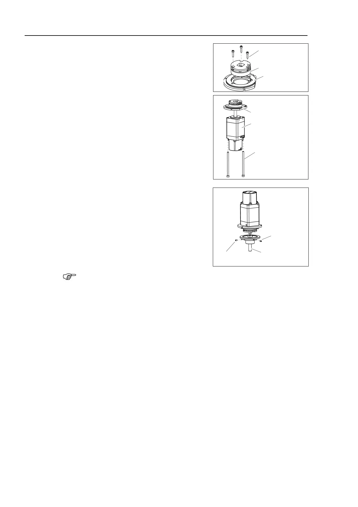
oint #4 Brake
the brake on the motor plate.
3-M2.5×10
Joint #4
Motor Plate
Brake
Mount the Joint #4 motor on
the motor plate.
the motor, make sure that the
passes through a gap of the motor
the motor, be careful not to
the brake harness in the space between the
and Joint #4 motor.
After the motor is mounted, bind
the brake
harness with a wire tie and fix it on the motor.
2-M4×70
Joint #4 Motor
Motor Plate
3)
extension shaft on the Joint #4 motor
while aligning the hub of the extension
to the brake disc.
Tighten one of the set screws vertically on the
flat
face of the extension shaft.
Insert a bushing into the other set screw hole to
prevent damage to the
extension shaft.
M3×5 Set Screw
+ M3 Bushing
Extension shaft
M3×5
Set Screw
When the brake disc is not aligned, manually adjust the position by following the
steps
1. C
onnect the connector: BR4.
2.
P
ress the brake release switch to release the brake.
3. M
anually adjust the brake disc so that the hole will be at the center.

 Loading...


