Maintenance 8. Joint #4
LS20-B Rev.4 139
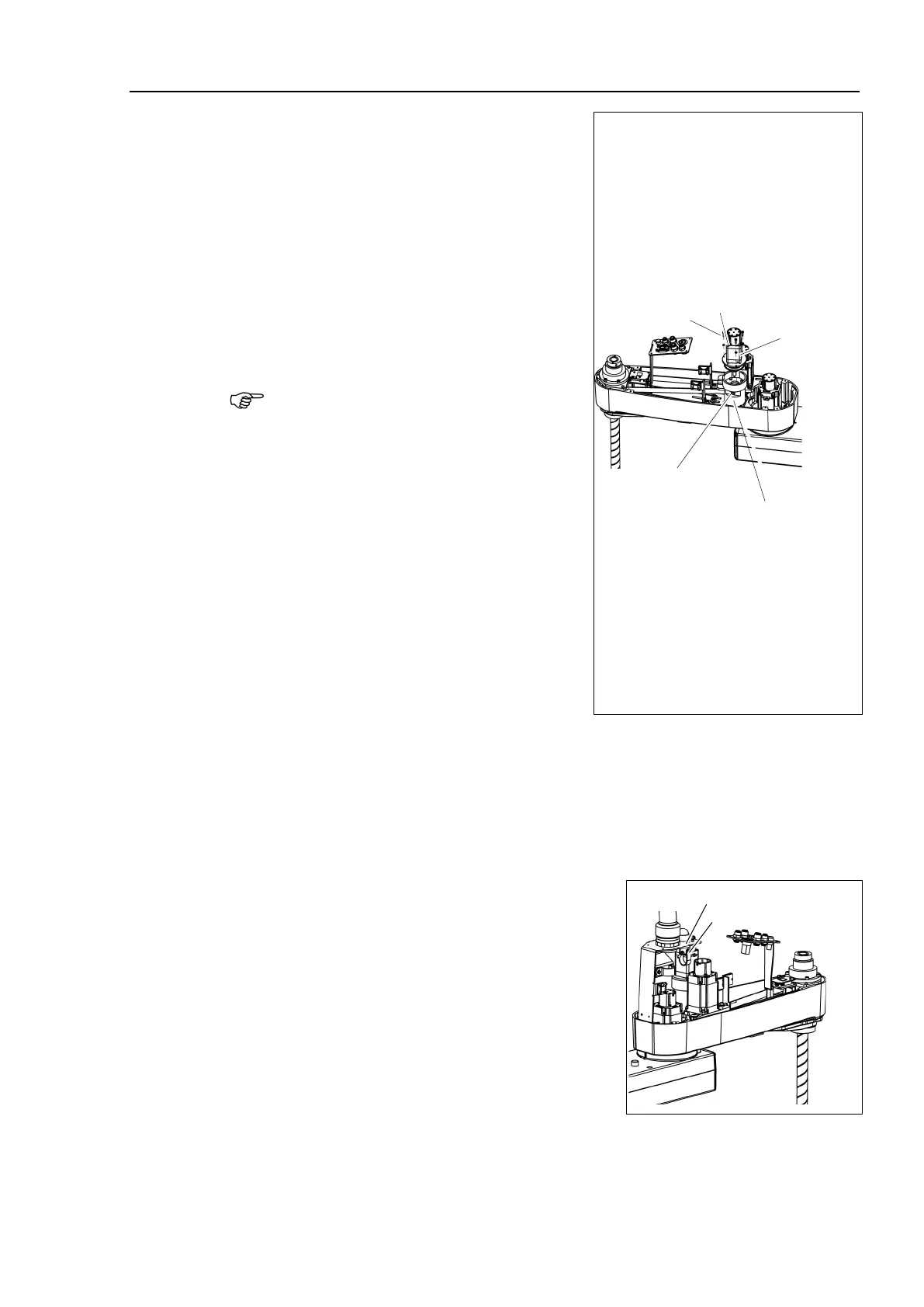
4)
Insert the extension shaft to the reduction
gear unit.
oint #4 motor cable is
looking from the front side
inserting the extension shaft, loosely
secure the motor plate on
the Joint #4 motor
bolts (M3×12), and loosen the
bolts (M4×70) to secure the
At this point, make sure that the motor
unit
can be moved by hand, and it will not tilt
when pulled.
Before fixing it to the reduction gear unit,
make sure to rotate Joint #4 reduction unit
two or three times from the output side.
Remove the cover of the hole for fixing the
, and then tighten the bolts to
the extension shaft on the reduction gear
Hole for fixing the
extension shaft
Joint #4
Reduction Gear Unit
ighten the bolts on the loosely secured
and the motor to fix Joint #4
on the reduction gear unit.
ount the cover of the hole for fixing the extension shaft.
the Duct Plate.
For details, refer to Maintenance 3. Covers.
Connect the following connectors
.
Connectors: BR4, X241, X41
clip band removed in the removal step
(5) and bind the cables to fix.
bend or pull the cables forcibly to allow
unnecessary strain on the cables.
the Arm Top Cover.
For details, refer to Maintenance: 3.1 Arm Top Cover.

 Loading...


