Maintenance 5. Arm #1
94 LS Rev.10
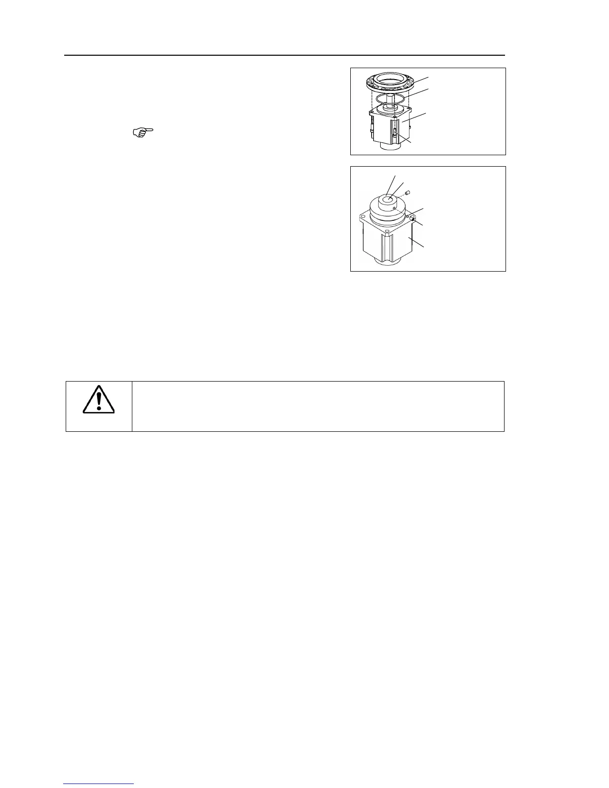
-ring on the motor mounting
surface and mount the motor flange.
waveform generator and motor.
Grease volume LS3: 4 g
LS6: 13 g
Mount the waveform generator on the Joint
align the end face of the
generator to the end face of the
one of the set screws vertically on
flat face of the motor shaft. Insert a
into the other set screw hole to
damage to the motor shaft.
A: Brass Bushing LS3: M4
LS6: M5
B: Set Screw LS3: 2-M4×6
LS6: 2-M5×6
CAUTION
■
See the figure above for the orientation of the waveform generator.
install the waveform generator properly.
Improper installation of the waveform
generator will result in improper function of the Manipulator.
-ring on the motor mounting surface and assemble the motor with
-ring on the motor flange and assemble the motor with the Joint #1
To insert the motor, turn it
slowly from side to side by hand and push in.
Connect the connector X10 to the resolver board.
Mount the Joint #1 unit on the Base.
Secure the Joint #1 motor cables facing toward the back of the Base.
-ring removed in the removal step (3) into the O-ring groove of the arm.
Then, mount the arm to the Joint #1 unit.
Connect the connector X110.
Mount the Connector Plate.
Maintenance: 3.3 Connector Plate.
Execute the calibration f
Maintenance: 13. Calibration.

 Loading...


