Maintenance 5. Arm #1
96 LS Rev.10
CAUTION
■
adjust (loosen or tighten) the mounting bolts between the flexspline and
cross roller bearing unit.
If the mounting bolts are adjusted, the flexspline and
cross roller bearing unit must be
aligned by the maker of the reduction gear unit.
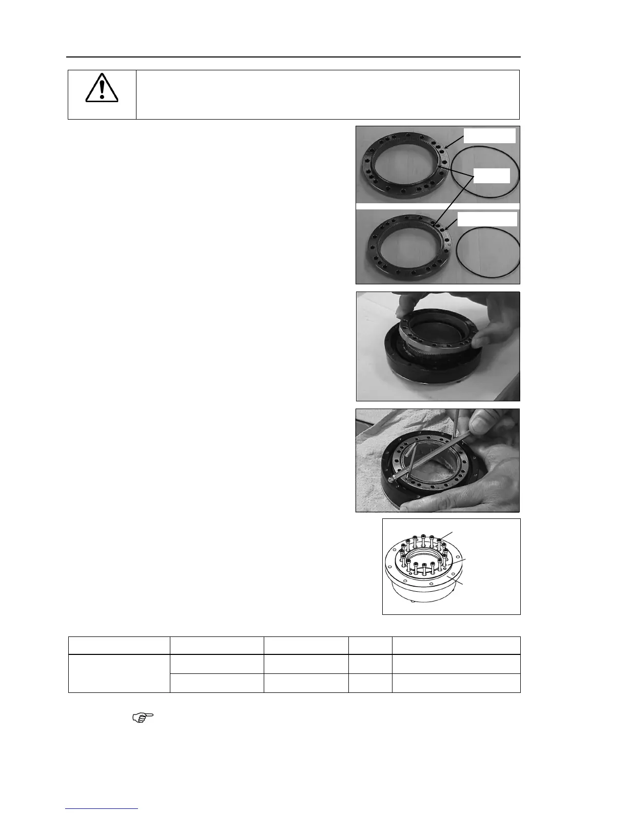
O-rings into the grooves on both
s of the new circular spline.
sure that the rings do not come out
Face the convex side of the circular spline
down,
and then fit it into the flexspline.
atch the screw holes on the inner ring of
the cross roller bearing unit and the
through holes of the circular spline.
the reduction gear flange to the circular
asten all bolts in a crisscross pattern so
the bolts will be fastened evenly. Then,
tighten each bolt securely
at the torque specified in
LS3: 16-M3×20
LS6: 16-M4×25
Item Manipulator type Bolt type Bolts Tightening torque
Joint #1 reduction
gear unit
LS3
M3×20 16
2.35 N⋅m (24 kgf⋅cm)
LS6
M4×25 16 5.4 N⋅m (55 kgf⋅cm)
careful not to apply too much force since it may damage the parts.

 Loading...


