Maintenance 6. Arm #2
100 LS Rev.10
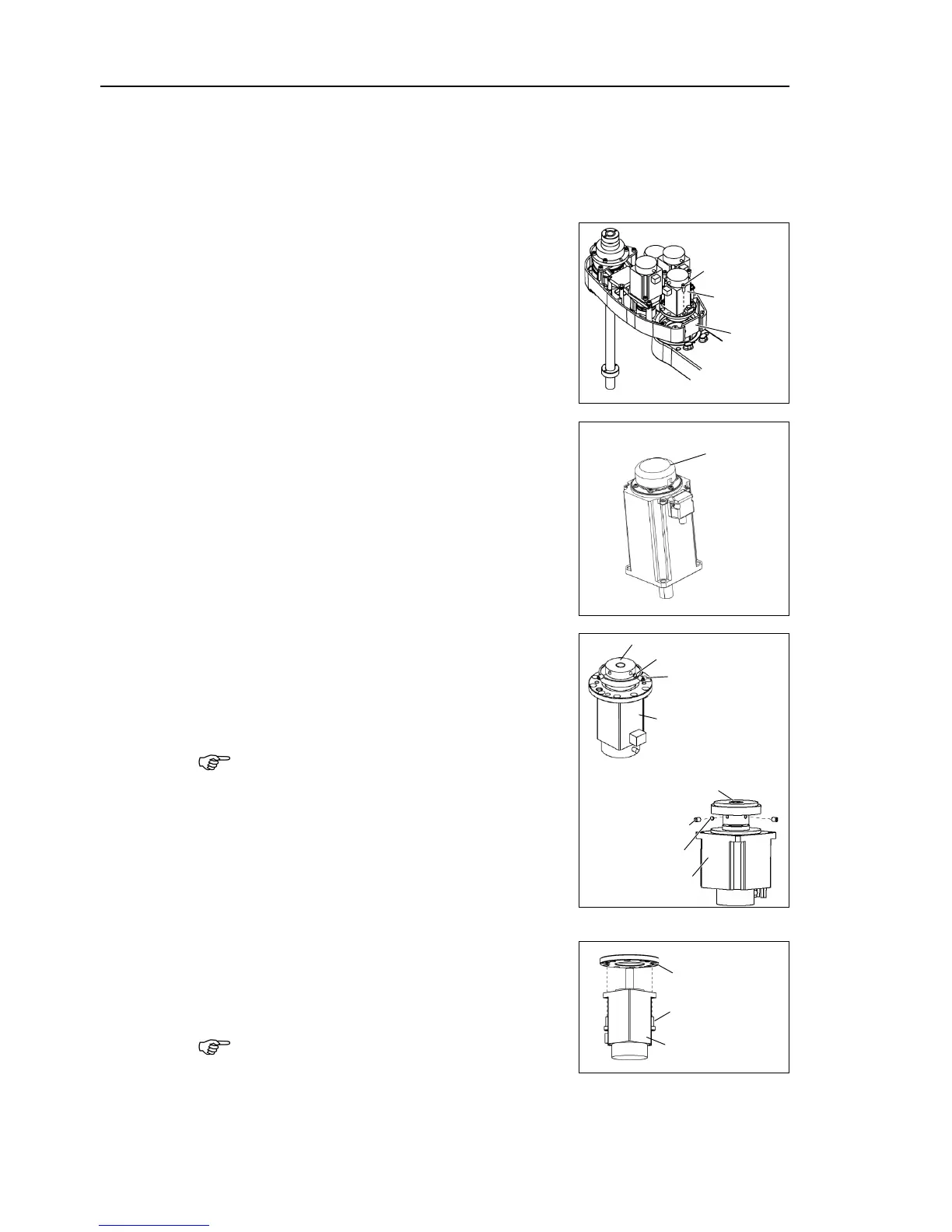
Cut off the wire tie binding the cables.
o not cut the wire tie (in the duct fittings outlet) that binds the cables
Disconnect the connectors X221
and X21. (Hold the claw to remove.)
the screws mounting the motor unit and
the Joint #2 motor unit from the
LS3: Motor flange mounting screw 3-M4×10
LS6: Motor mounting screw 4-M4×12
the motor smoothly, move the Arm #2
hand while pulling the motor.
When replacing the motor of the Joint #2,
remove the cap from the old motor and install it
to the new one.
If the Manipulator is operated while the cap is
not installed, the motor may be
entering of the foreign materials into the rotating
part of
the motor sensor and interference of the
rotating part and the cables.
the waveform generator from the Joint
There is a brass bushing in one of the
Be sure to keep the bushing.
Orientation of the waveform generator is
opposite from that of LS3. Set screws are
at the motor side.
Remove the motor flange from the Joint #2
motor.
does not have a motor flange.

 Loading...


