Maintenance 7. Arm #3
114 LS Rev.10
a new Z belt through the shaft.
around the spline plate pulley.
Secure the spline plate with 3 screws.
Loosely secure the spline plate on the Arm
#2 and move the shaft up and down several
times before firmly secure the spline plate.
the Joint #3 motor unit back in the arm.
Pass the brake cable and special power
supply through the Z belt.
Place the Z belt around the Z1 pulley and Z2
pulley, with the gear grooves of the belt
fitting into grooves of the pulleys
completely.
Loosely secure the Joint #3 motor unit to the
Arm #2.
Secure the ground wire with a mounting screw.
At this point, make sure that the Joint #3 motor
unit can be moved by hand, and it
not tilt when pulled. If the unit is secured too loose or too tight, the belt will
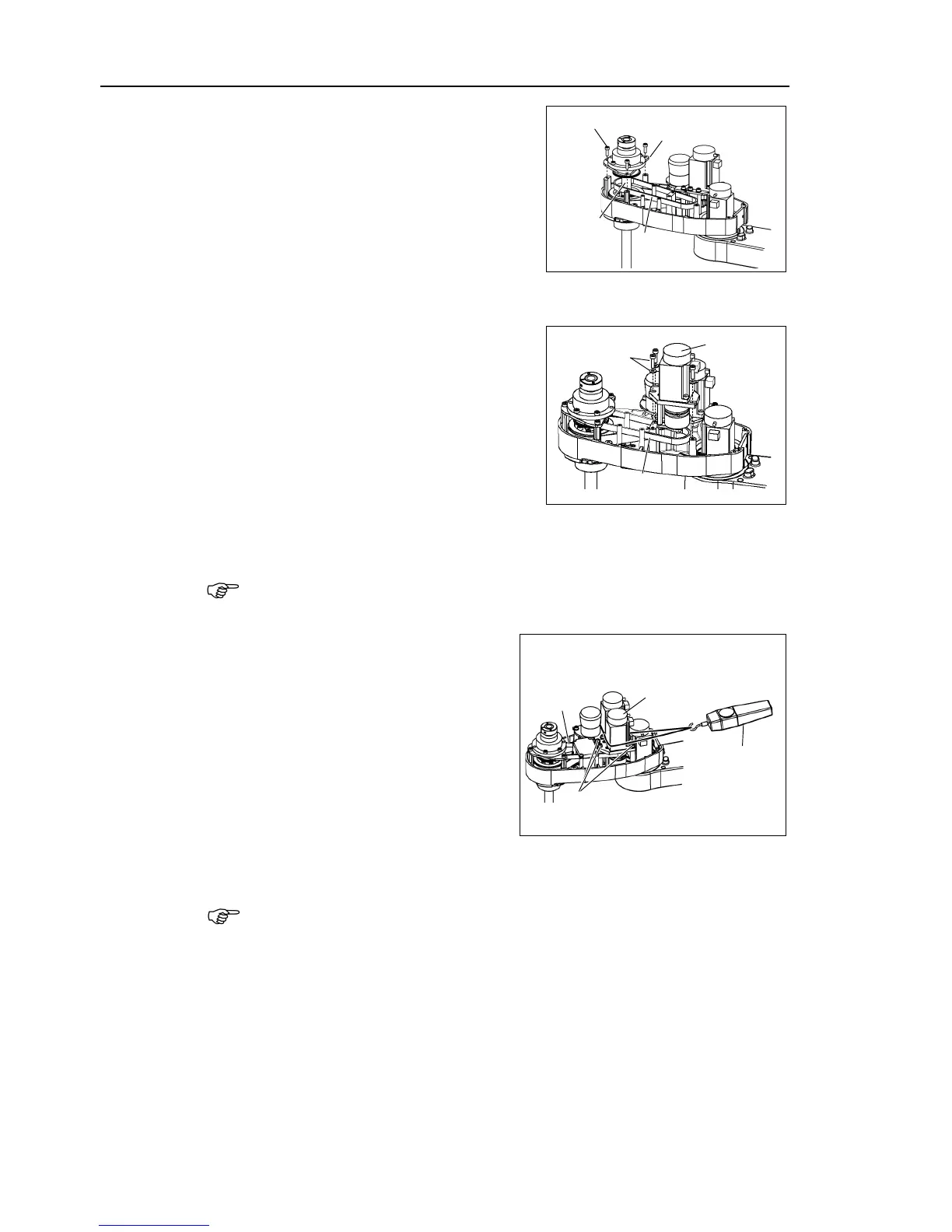
Apply the proper tension to the Z belt,
and then secure the Joint #3 motor unit.
a suitable cord or string around the
. Then, pull the cord using a force
or similar tool to apply the
specified tension shown in the figure on
the right
.
Z belt tension
69 N (7.0 ± 0.5 kgf)
check belt tension with the tension meter, refer to Maintenance:
7.4 Checking the
Timing Belt Tension (Z Belt).
Maintenance: 11.3 Replacing the Control Board.
X231, X241, X31, X35, X41.
Maintenance: 3.5 User Plate.
the cables with a wire tie in their original positions as before removed in
step (7). Do not allow unnecessary strain on the cables.

 Loading...


