Maintenance 8. Arm #4
124 LS Rev.10
Mount the motor plate to the Joint #4 motor.
otor cables must be in the
2-M4×8
Set Screw
+ Bushing
the pulley to the Joint #4 motor.
Be sure to fit the end face of the pulley to
end face of the motor shaft.
screws vertically on the flat face of the motor shaft.
bushing into the other set screw hole to prevent damage to the motor shaft.
Place the pulley around the U1 belt and
p
lace the Joint #4 motor unit in the upper
Loosely secure the Joint #4 motor unit to
Arm
the motor unit can be moved by
, and it will not tilt when pulled. If the
secured too loose or too tight, the belt
grooves of the belt are fit
into those of the pulleys completely.
Apply the proper tension to the U1 belt and
secure
a suitable cord or string around the
Joint #4 motor unit near its mounting plate
ull the cord using a force gauge or
similar tool to apply the specified tension
shown in the figure
.
U1 belt tension
LS3 = 39 N (4.0 ± 0.5 kgf)
LS6(a) = 39 N (4.0 ± 0.5 kgf)
LS6(b) = 58 N (5.9 ± 0.5 kgf)
check belt tension with the tension meter, refer to Maintenance: 8
.4 Checking the
Timing Belt Tension (U1, U2 Belt).
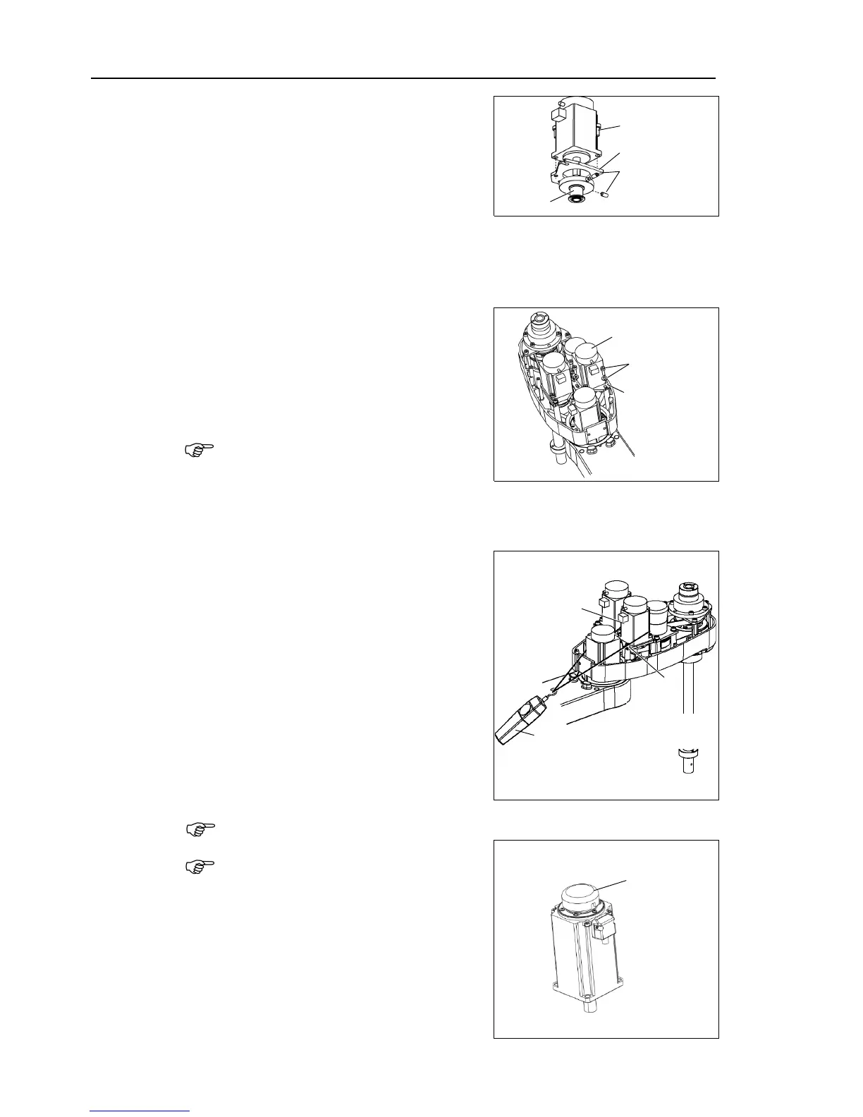
When replacing the motor of the Joint #4,
remove the cap from the old motor and
install it to the new one.
If the Manipulator is operated while the cap
is not installed, the motor may be
due to entering of the foreign materials into
the rotating part of
interference of the rotating part and the
cables.

 Loading...


