Maintenance 8. Arm #4
LS Rev.10 129
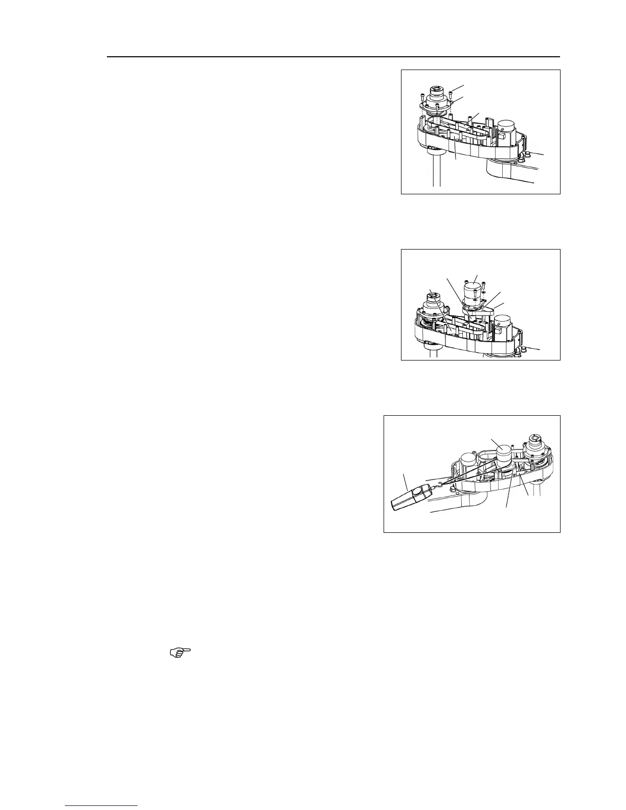
Hold up the spline plate and set the U2
the gear grooves of the belt are
fit into those of the pulleys
Hold up the spline plate and set the Z belt
around the Z2 pulley.
the gear grooves of the belt are
fit into those of the pulleys
Loosely secure the spline plate on the Arm #2
the shaft up and down
several times
before firmly secure the spline plate.
belt on the large pulley of
the Joint #4 intermediate shaft unit, set the
U2 belt in the Arm #2 on the small pulley
and put them on the Arm
the gear grooves of the belts are
fit into those of the pulleys
Joint #4
Intermediate Shaft Unit
Loosely secure the Joint #
4 intermediate shaft unit.
the unit can be moved by hand, and it will not tilt when pulled. If the
secured too loose or too tight, the belt will not have the proper tension.
Apply the proper tension to the U2 belt,
and then secure the Joint #4
intermediate shaft unit.
ass a suitable cord or string around the
4 intermediate shaft unit near its
Then, pull the cord using
tool to apply the specified
tension shown in the figure on
the right.
U2 belt tension:
LS3 = 69 N (7.0 ± 0.5 kgf)
LS6(a) = 69 N (7.0 ± 0.5 kgf)
LS6(b) = 102 N (10.4 ± 0.75 kgf)
Joint #4
Intermediate Shaft Unit
check belt tension with the tension meter, refer to Maintenance: 8
.4 Checking the
Timing Belt Tension

 Loading...


