Maintenance 8. Arm #4
130 LS Rev.10
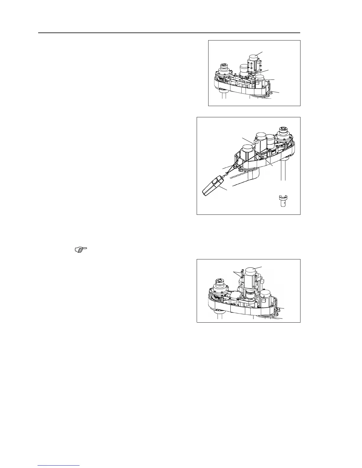
Mount the Joint #4 motor unit on the Arm
#2 with the U1 belt around the pulley.
Loosely secure the Joint #4
Make sure the motor unit can be moved by
hand, and it will not tilt when pulled. If
the unit is secured too loose or too tight, the
belt will not have the proper tension.
Apply the proper tension to the U1 belt
and secure the Joint #4 motor unit.
ass a suitable cord or string around the
#4 motor unit near its mounting
Then, pull the cord using
or similar tool to apply the
in the figure on the right.
U1 belt tension
LS3 = 39 N (4.0 ± 0.5 kgf)
LS6 (a) = 39 N (4.0 ± 0.5 kgf)
LS6 (b) = 58 N (5.9 ± 0.5 kgf)
check belt tension with the tension meter, refer to Maintenance: 8
.4 Checking the
Timing Belt Tension
Put the Joint #3 motor unit back in the
arm.
Pass the brake cable and special power
supply through the Z belt.
Set the Z belt around the Z1 pulley and
Z2
pulley, with the gear grooves of the
belt fitting into grooves of the pulleys
completely.
Loosely secure the Joint #3 motor unit to Arm #2.
Secure the ground wire with a mounting screw.
the motor unit can be moved by hand, and it will not tilt when
f the unit is secured too loose or too tight, the belt will not have the proper tension.

 Loading...


