EPSON Stylus C50/C60/C61/C62 Revision C
Disassembly and Assembly Disassembly 112
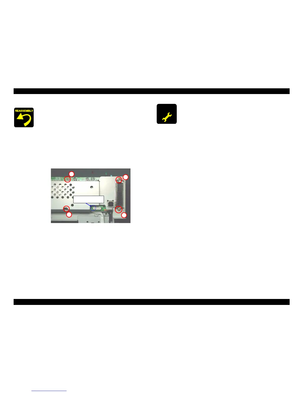
When assembling the Main board shield plate on the Main
board,
When the M/B mounting plate is removed from the Printer
mechanism, the hook of the M/B mounting plate deforms.
Therefore, you have to use new one.
Make sure that the metal fittings for locking the Parallel
interface is on its shield plate.
Fasten four screws (C.B.S. SCREW 3x6 F/Zn,
C.B.S. SCREW 3x14 F/Zn) for securing the Main board
shield plate and the Main board to the Main frame in the
order indicated in the following figure.
Figure 4-46. Circuit board assembling
Tightening torque for each screw is as follows.
•
C.B.S. SCREW, 3x6, F/Zn (2 pcs)
: 9 ± 1 kgf.cm
•
C.B.S. SCREW, 3x14, F/Zn (2 pcs) : 9 ± 1 kgf.cm
Make sure to connect all cables to the connectors (CN2, CN4,
CN7, CN8, CN9, CN12) on the Main board in the correct
direction. (Refer to Figure 4-46)
3
1
2
4
Blue line marking side
for P/S cable
When assembling the SW button,
Make sure that two hooks of the SW button is correctly fixed
to the Main frame.
When replacing the Main board with new one, perform the
following service items.
Before removing the Main board, connect the parallel I/F or
USB cable and try to read out the following data by using the
Adjustment program. If this operation succeeds, replace the
Main board and write the read out data to new Main board
by using the Adjustment program. (Refer to Chapter 5)
1) Ink consumption counter (Address : 10H ~ 1FH)
2) Waste drain ink pad counter (Address : 0AH ~ 0BH)
3) Head ID (Address : 3FH ~ 4CH)
4) Gap adjustment (Bi-d adjustment)
(Address : 2AH ~ 2BH, 33H ~ 38H)
5) Top margin adjustment (Address : 2EH)
6) 1st dot position adjustment (Address : 39H)
7) USB ID (Address : 4DH
~
5EH)
8) Market ID (Address: 5FH)
In case that the above mentioned data are not able to be read
out from the defective Main board, perform the following
service items after replacing the Main board with new one.
1) Replace the both ink cartridges with brand new one for
the Ink consumption counter.
2) Replace the Waste drain ink pad with new one for the
Waste drain ink pad counter.
3) Input the Head ID
4) Adjust the Bi-D alignment
5) Adjust the Top margin
6) Adjust the 1st dot position
7) Input the serial number for USB ID
8) Input EEPROM initial setting value for the Market ID
 Loading...