EPSON Stylus C50/C60/C61/C62 Revision C
Disassembly and Assembly Disassembly 115
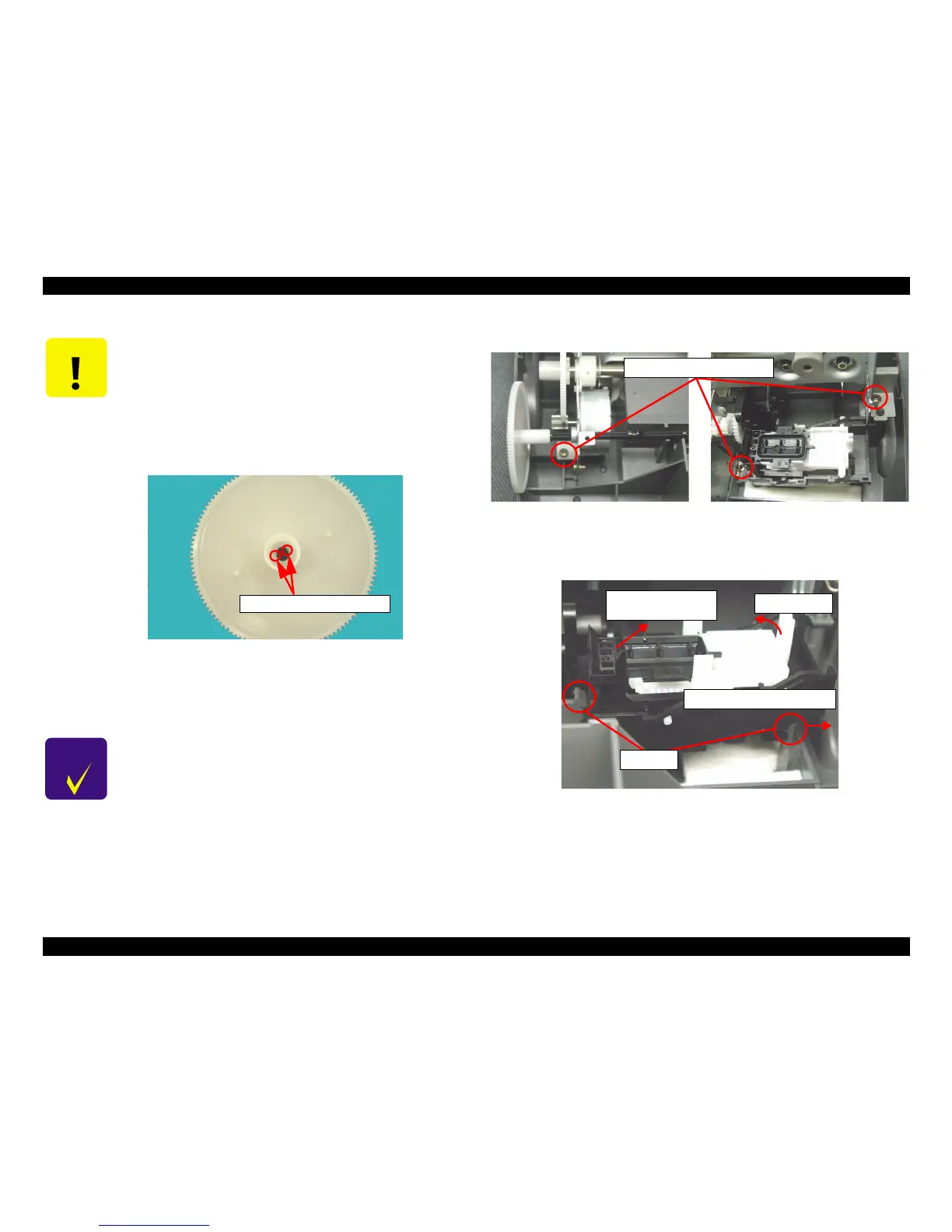
8. Remove three screws (C.B.P-TITE SCREW 3x8 F/Zn) for securing the Printer
mechanism to the Lower housing.
Figure 4-52. Printer mechanism removal (1)
9. Release two hooks for securing the Cap unit to the Lower housing in the order
indicated in the following figure.
Figure 4-53. Cap unit removal
CAUTION
Do not damage the Spur gear 60 when sliding the Paper eject
roller to the left side.
Do not remove Paper eject roller shaft from the Spur gear 60
completely.
When
the Paper eject roller shaft from Spur gear 60, the
hooks on the Paper eject roller shaft are damaged.
Therefore, do not use them again because the paper feeding
accuracy is lowered.
Figure 4-51. Hooks on the Paper eject roller shaft
The Paper eject roller and the Spur gear 60 is not established for
service part.
CHECK
PO INT
When removing the screw for securing the Printer mechanism
on the left side of the printer, if the Paper eject roller is in the
usual setting position, the screwdriver may damage the Spur
gear 60.
Hooks on the Paper eject roller shaft
C.B.P-TITE SCREW, 3x10, F/Zn
Step1) Remove hook to the right
Step2)
Lift up
Step3) Pull the Cap unit
to the left side
Hooks
 Loading...