Epson Stylus C58/C59/ME 2/C79/D78/C90/C91/C92/D92/T20/T20E/T23/T26/S20/T10/T11/ME 30/T21/T24/T27/S21 Revision E
DISASSEMBLY/ASSEMBLY Disassembling Printer Mechanism 49
Confidential
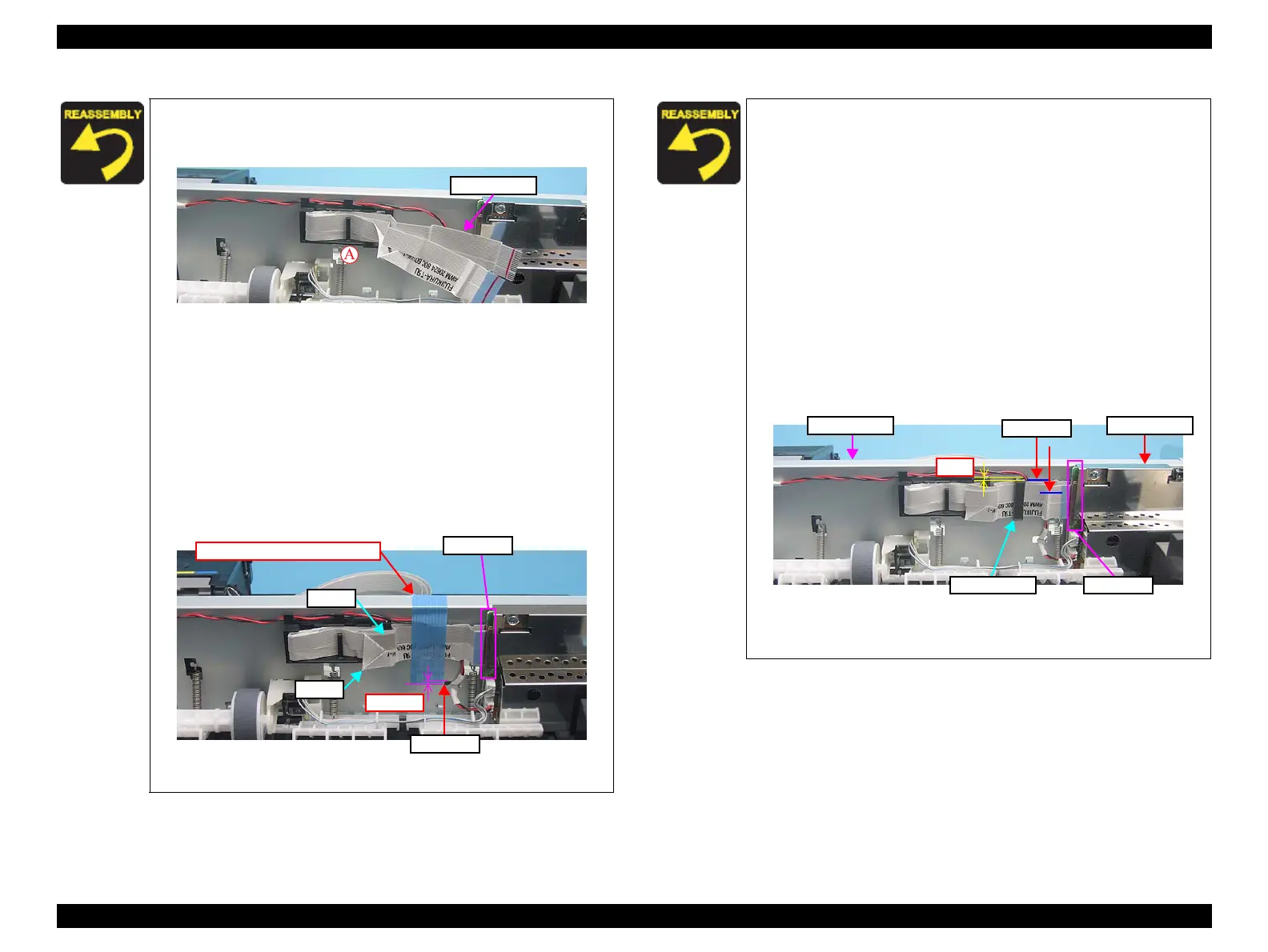
>> From the previous page.
3. Fold back the Head FFC and secure it with Rib A again.
Figure 4-31. Installing Head FFC (3)
4. Connect the Head FFC to CN1, CN3 of the Main Board.
(see “ 4.4.1 Main Board ” (p.40))
5. Arrange FFC1 on top of FFC2.
6. Secure the Head FFC with a Strong tape by the following
standard.
• Size: 60mm (L) x 18mm (W)
• The tape must be attached vertically to the Head FFC.
• The lower end of the tape must be 1-2 mm below the upper
side of the hook hole as shown in the figure.
Figure 4-32. Installing Head FFC (4)
CN1,CN3
Hook hole
Strong Tape (60mm x 18mm)
Epson Stylus C58/C59/ME 2's Case
1. Put the Head FFC through the Hole of the Main Frame.
(see Figure 4-29 (p.48))
2. Secure the Head FFC with Rib A, and B.
(see Figure 4-29 (p.48))
3. Fold back the Head FFC and secure it with Rib A again.
(see Figure 4-31 (p.49))
4. Put the Head FFC through the Ferrite Core with double
sided tape behind.
5. Connect the Head FFC to CN1, CN3 of the Main Board.
(see “ 4.4.1 Main Board ” (p.40))
6. Secure the Ferrite Core to the Main Frame with double
sided tape by the following standard.
• The top end of the Ferrite Core must be 1mm above the
horizontal marking on the Main Frame.
Figure 4-33. Installing Head FFC (5)
>>To be continued to the next page.
Ferrite Core CN1,CN3
Main Frame
Marking
Main Board