EPSON Stylus COLOR 440, 640, and 740 Chapter 1 Product Description
20
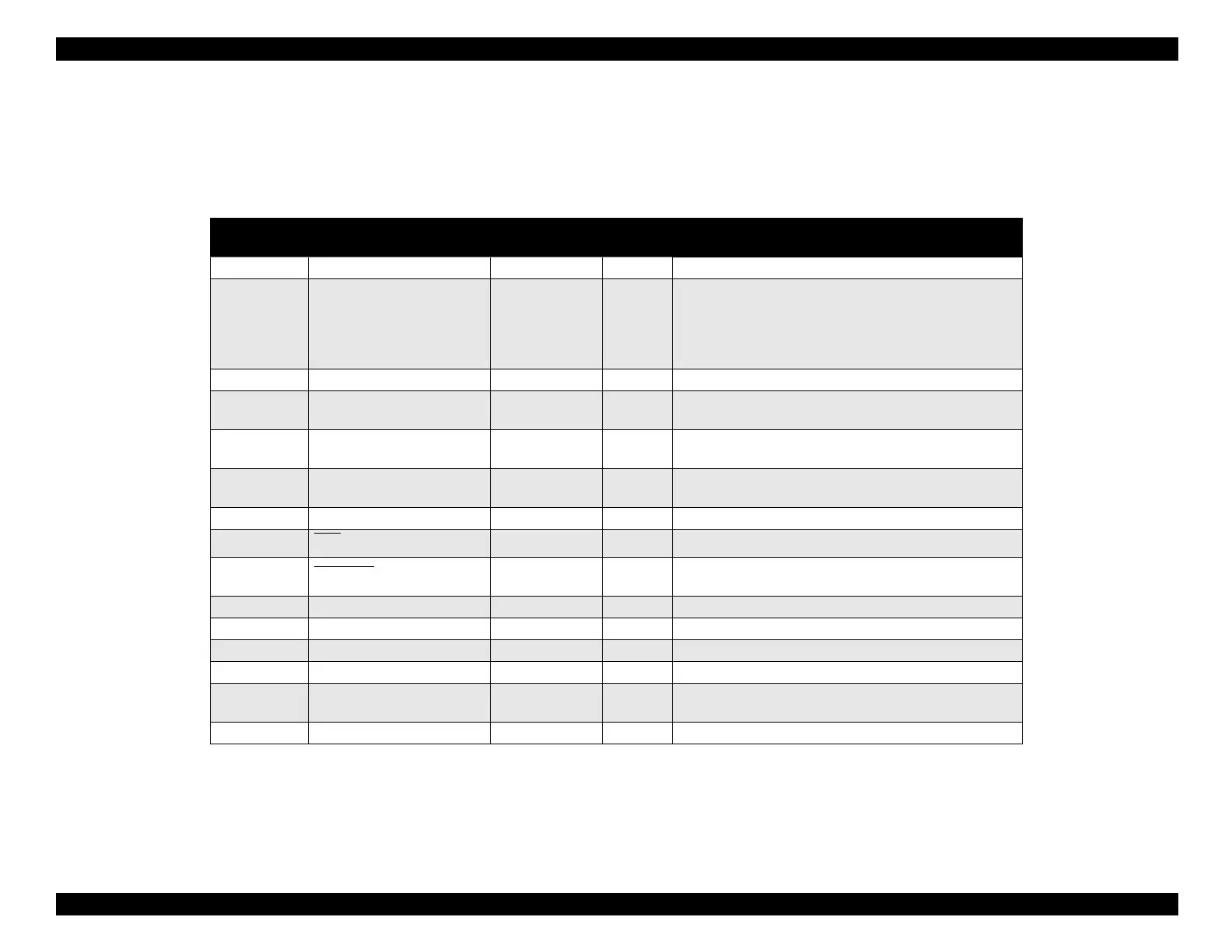
Table 1-12 shows pin assi
nments for the reverse channel.
Reverse
channel is the mode in which all data is transferred from the printer to
the computer.
For these si
nals, a twisted pair line is used, and the
return side is connected to the si
nal GND.
Table 1-12. Pin Assignments for Reverse Channel
Pin No. Signal Name
Return GND
Pin
In/Out Functional Description
1 HostClk 19 In Host clock signal.
2 to 9 Data0 to Data7 20 to 27 In
The DATA0 through DATA7 signals represent data
bits 0 through 7. Each signal is at HIGH level when
data is logical 1, and at a LOW level when data is
logical 0. These signals are used to transfer the 1284
extensibility request values to the printer.
10 PrtClk 28 Out Printer clock signal.
11 PtrBusy, Data Bit-3,7 29 Out
Printer busy signal and reverse channel transfer data
bit 3 or 7.
12 AckData Req, DataBit-2,6 28 Out
Acknowledge data request signal and reverse channel
transfer data bit 2 or 6.
13 Xflag, DataBit-1,5 28 Out
X-flag signal and reverse channel transfer data bit 1 or
5.
14 HostBusy 30 In Host busy signal.
31 INIT 30 In
Not used.
32 DataAvail
, DataBit-0,4 29 Out
Data available signal and reverse channel transfer
data bit 0 or 4.
36 1284-Active 30 In 1284 Active Signal
18 Logic-H — Out Pulled up to +5 V via 3.9K ohm resistor.
35 +5 V — Out Pulled up to +5 V via 3.3K ohm resistor.
17 Chassis GND — — Chassis ground.
16,33, 19 to
30
GND — —
Signal ground.
15,34 NC — — Not connected.
Notes: In/Out refers to the direction of signal flow from the printer’s point of view.
An overscore above a signal name means that signal is active LOW.

 Loading...


