EPSON Stylus COLOR 440, 640, and 740 Chapter 1 Product Description
21
The followin
are
eneral notes on the parallel interface:
The Return GND Pin column in Tables 1-10 and 1-12 indicates a
twisted pair return, and is used for all control si
nals except Lo
ic-H,
+5 V, Chassis GND, and NC. The return side is connected to GND
pins 16, 33, and 19 to 30
in the twisted pair return. Since these
cables are shielded,
ou can reduce electrostatic noise b
connectin
them to Chassis GND in both the printer and computer.
Interface conditions are based on TTL lo
ic levels. Rise and fall times
should be less than 0.2
µ
s.
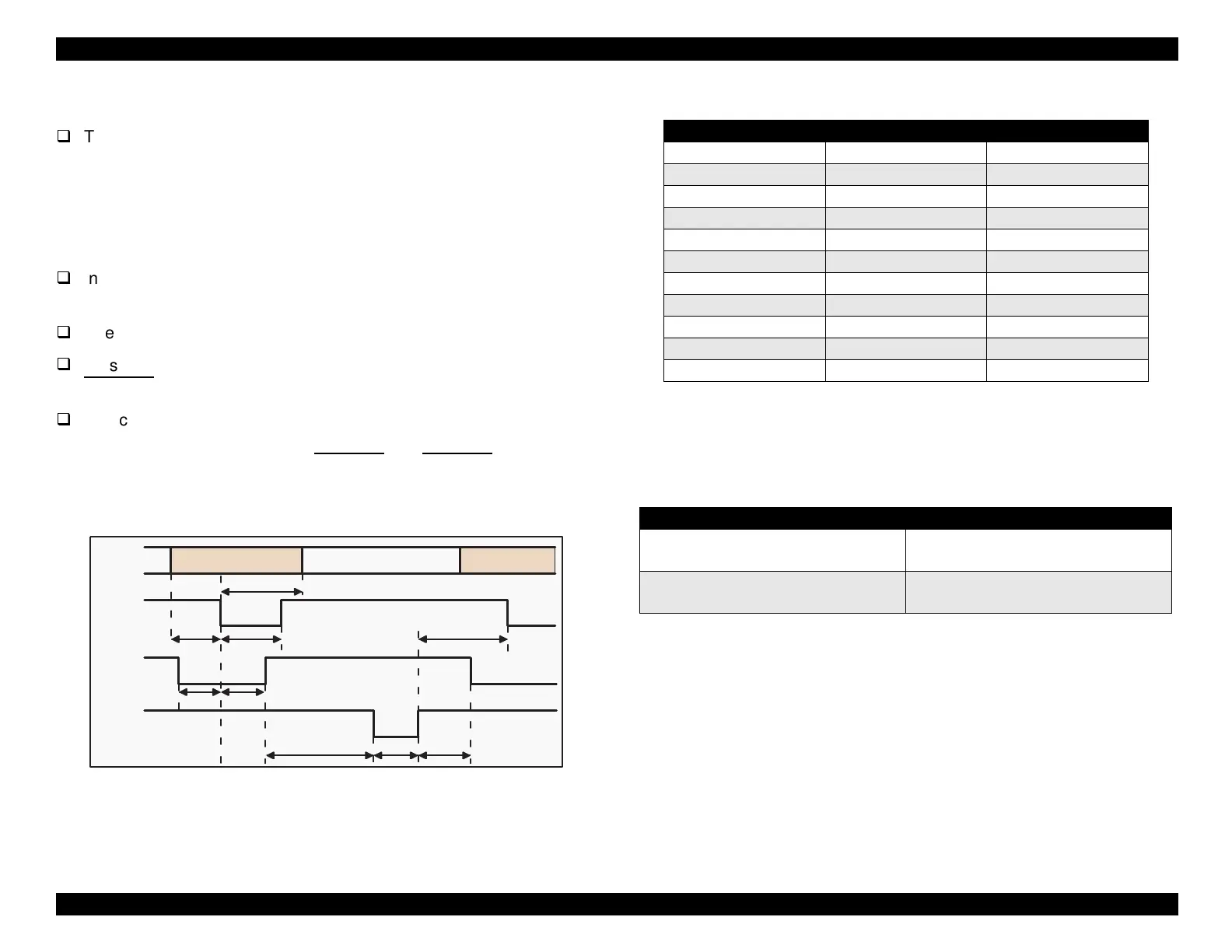
See Fi
ure 1-9 for the transmission timin
of each si
nal.
Be sure to perform data transmission onl
after confirmin
that the
ACKNLG
and BUSY si
nals are LOW.
You can perform a print test without usin
external e
uipment. Set
the 8-bit data si
nals
pins 20 throu
h 27
to the appropriate word
code and connect them to the ACKNLG
and STROBE si
nals.
Figure 1-9. Data Transmission Timing for the Forward Channel
Table 1-13.
Maximum and Minimum Timing for Data Transmission
* Rise and fall time of every output signal.
** Rise and fall time of every input signal. Typical timing for the tack
parameter is shown in Table 1-14 below.
Table 1-14. Typical Tack Timing
Byte Data n
Byte Data n+1
Thold
Tsetup
Tstrb
Tnext
Tready Tbusy
Treply
Tack Tnbusy
Data
/STROBE
BUSY
/ACKNLG
Parameter Minimum Maximum
tsetup 500ns —
thold 500ns —
tstb 500ns —
tready 0 —
tbusy — 500ns
tt-out* — 120ns
tt-in** — 200ns
treply 0 —
tack 500ns 10us
tnbusy 0 —
tnext 0 —
Parallel Interface Mode Typical Tack Timing
High speed
2
µ
s (Stylus COLOR 440 and 640)
1
µ
s (Stylus COLOR 740)
Normal speed
4
µ
s (Stylus COLOR 440 and 640)
3
µ
s (Stylus COLOR740)

 Loading...


