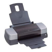
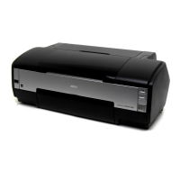
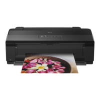
EPSON Stylus Photo 1390/1400/1410 Revision B
DISASSEMBLY AND ASSEMBLY Disassembly/Assembly Procedures 120
6. Remove the PG Grounding Spring from the cutout of the Main Frame, and remove
the PF Grounding Spring from the groove of the PF Roller Shaft.
Figure 4-125. Removing the PF Grounding Spring
7. Make sure that the Left Parallelism Adjust Bushing is not protruding from the
cutout of the Main Frame. If it is protruding, loosen the C.B.S. (P4) 3x8 screw that
secures the Left Parallelism Adjust Bushing, and slide it to prevent the Left
Parallelism Adjust Bushing from becoming hooked on the cutout.
Figure 4-126. Rotating the Left Parallelism Adjust Bushing
8. Remove the Guide Pin of Left Bushing 8 from the Main Frame using tweezers,
and rotate the Bushing upwards to align with the cutout on the Main Frame.
Figure 4-127. Rotating the Left Bushing 8
9. Remove the E-ring from the PF Roller Shaft with a flat-blade screwdriver, and
slide Left Bushing 8 to the inside of the Printer Mechanism.
Figure 4-128. Removing the Left Bushing 8
Rear
Cutout
PF Grounding Spring
PF Roller Shaft
Groove
6) C.B.S. (P4) 3x8
(5±1 kgf.cm)
Left Parallelism
Adjust Bushing
Cutout
C A U T I O N
When performing the following procedure, take care not to lose the
E-ring.
Guide pin
Left Bushing 8
Cutout
E-Ring
PF Roller Shaft

 Loading...


