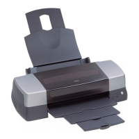
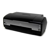
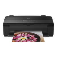
EPSON Stylus Photo 1390/1400/1410 Revision B
DISASSEMBLY AND ASSEMBLY Procedure Specific to Stylus Photo 1390 128
4.3 Procedure Specific to Stylus Photo 1390
This section describes disassembly procedures of the Upper Housing and the Paper EJ
Frame Assy of Stylus Photo 1390.
4.3.1 Upper Housing
1. Open the Printer Cover and the Paper Support.
2. Remove the two C.B.S. 3x6 screws, and open the Front Cover.
Figure 4-146. Opening the Front Cover
3. Remove the Side Housing. See Section 4.2.1.2 on page 78.
4. Remove the four C.B.P. 3x10 screws, three C.B.S. 3x6 screws, and two C.B.P.
3x10 screws that secure the Upper Housing.
Figure 4-147. Screws that Secure the Upper Housing
Printer Cover
2) C.B.S. 3x6
(6±1 kgf.cm)
Front Cover
Paper
Support
1
Guide Pin
3
Guide Pin
5
4
9
Tab
2
6
Tab
7
8
1) C.B.P. 3x10
(6±1 kgf.cm)
2) C.B.S. 3x6
(6±1 kgf.cm)
15) C.B.P. 3x10
(6±1 kgf.cm)
Upper
Housing
Front Cover

 Loading...


