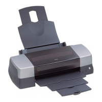
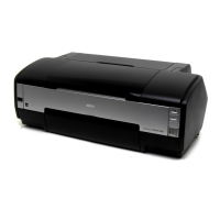
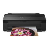
EPSON Stylus Photo 1390/1400/1410 Revision B
APPENDIX Connector Summary 160
Table 7-7. Connector CN6: CR Motor
Pin Signal I/O Function
1 CR-A O CR motor drive signal (phase A)
2 CR-B O CR motor drive signal (phase B)
Table 7-8. Connector CN7: PF Motor
Pin Signal I/O Function
1 PF-A O PF motor drive signal (phase A)
2 PF-B O PF motor drive signal (phase B)
Table 7-9. Connector CN8: Pump Motor
Pin Signal I/O Function
1 PUMP-A O Pump motor drive signal (phase A)
2 PUMP-B O Pump motor drive signal (phase B)
3 PUMP-/A O Pump motor drive signal (phase /A)
4 PUMP-/B O Pump motor drive signal (phase /B)
Table 7-10. Connector CN9: APG Motor
Pin Signal I/O Function
1 APG-A O APG motor drive signal (phase A)
2 APG-B O APG motor drive signal (phase B)
Table 7-11. Connector CN10: Printhead
Pin Signal I/O Function
1 TH I Head temperature signal (AN1)
2 SI3 O HSO3
3 GND – Ground
4 SI2 O HSO2
5 GND – Ground
6 SI1 O HSO1
7 GND – Ground
8 GND2_3 – Ground
9 COMB_2 – Trapezoid wave
10 GND2_1 – Ground
11 COMA_3 – Trapezoid wave
12 GND2_2 – Ground
13 COMA_1 – Trapezoid wave
Table 7-12. Connector CN11: Printhead
Pin Signal I/O Function
1 GND2_1 – Ground
2 COMA_2 – Trapezoid wave
3 GND2_3 – Ground
4 COMB_1 – Trapezoid wave
5 GND2_2 – Ground
6 COMB_3 – Trapezoid wave
7 GND – Ground
8 VDD2 – +3.3V
9 CH_B O EXHCH (head CH_B)
10 GND – Ground
11 SCK O Serial clock signal
12 GND – Ground
13 XHOT I Head temperature signal

 Loading...


