EG_GenPro425e_1103_UG_001_UK.docx
Descriptions and non-contractual illustrations in this document are given as an indication only.
ercogener reserves the right to make any modifications.
Dct_427_02
3.4 Power supply
If the battery option is present, the fact of removing the power supply +V
DC
will not turn the
modem OFF. For this, see the § 5.2 Turning the device OFF.
3.4.1 Power supply cables
The modem is powered with the cable supplied with the equipment (ERCOGENER P/N: 4402000107 or
4402304215). (See ANNEX 1 - 4-pin Micro-FIT cable without fuse)
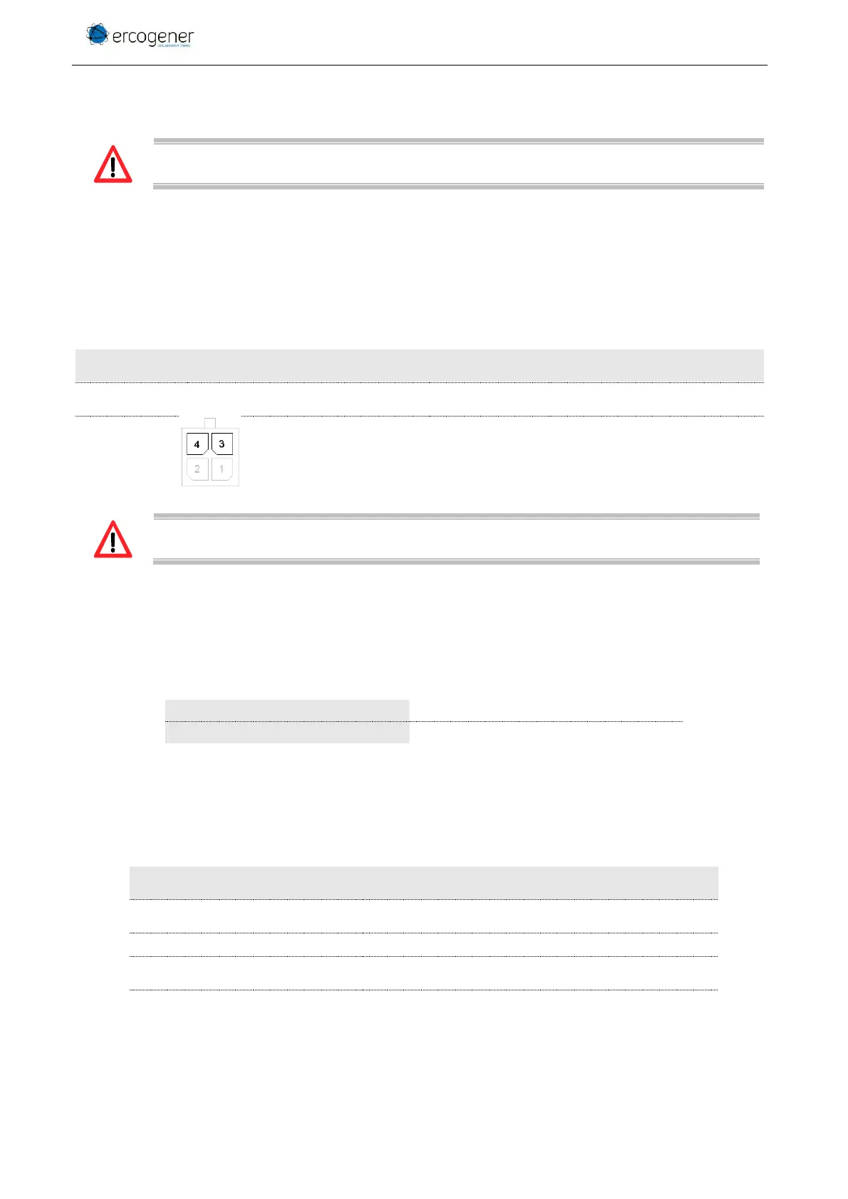
Table 7 : Description of power supply pins
Corresponds to wires
4 - Red for +V
DC
3 - Black for GND
See ANNEX 1 - ANNEX 1 - 4-pin Micro-FIT cable without fuse.
The pins 1 and 2 are used for the functions Input/Output.
The power supply to the modem is done only via the pins 4 (+V
DC
) and 3 (GND).
3.4.2 Power supply
The modem must be powered by an external DC voltage (+V
DC
) PS1 (max 15W) between:
The modem is also internally protected against voltage peaks of more than 32 V
DC
.
The following table describes the consequences of an overvoltage or drop of voltage on the modem.
Table 8 : Effects of power supply defect
▪ Voltage falls below 7.2V
▪ The functioning and the radio communication are not
guaranteed.
▪ Battery charge will not be ensured.
▪ Voltage above 32V (Punctual
peaks)
▪ The modem guarantees its own protection.
▪ The modem is protected by an internal resettable
fuse.