EG_GenPro425e_1103_UG_001_UK.docx
Descriptions and non-contractual illustrations in this document are given as an indication only.
ercogener reserves the right to make any modifications.
Dct_427_02
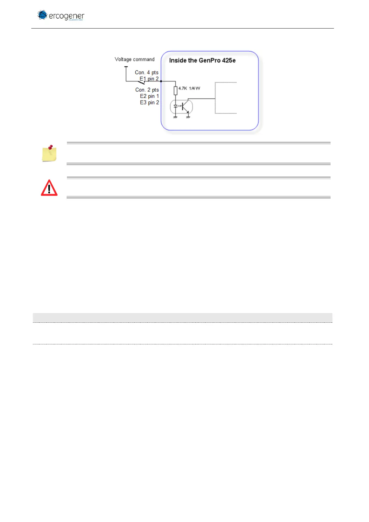
Figure 15 : Internal electric scheme of opto-coupled inputs
The minimum command voltage for the detection is: 3.5 V
The maximum command voltage is: 35 V
3.9.1.1 Inputs functioning
This function can also be controlled with AT commands:
AT+GPIOGET This command is used to read the inputs. The reading is done with the following format:
AT+GPIOGET=<n> with:
<n> = 7 : reading input 1
8 : reading input 2
9 : reading input 3
Examples:
Input 1 read at 0, command voltage > 3.5V on
input 1
Input 3 read at 1, the input 3 is connected to
GND