EG_GenPro425e_1103_UG_001_UK.docx
Descriptions and non-contractual illustrations in this document are given as an indication only.
ercogener reserves the right to make any modifications.
Dct_427_02
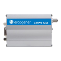
3.9.3 Analog input 0-10V (option)
The option Analog input 0-10V provides a second analog input able to measure a voltage between 0 and
10V with GND reference.
Table 29 : Description of analog input 0-10V
1 Connector 2 pins
3 Connector 4 pins
Corresponds to wires
1 - Yellow for ANA1
3 - Black for GND
See ANNEX 1 - ANNEX 1 - 4-pin Micro-FIT cable without
fuse.
See ANNEX 2 - 2-pin Micro-FIT cable.
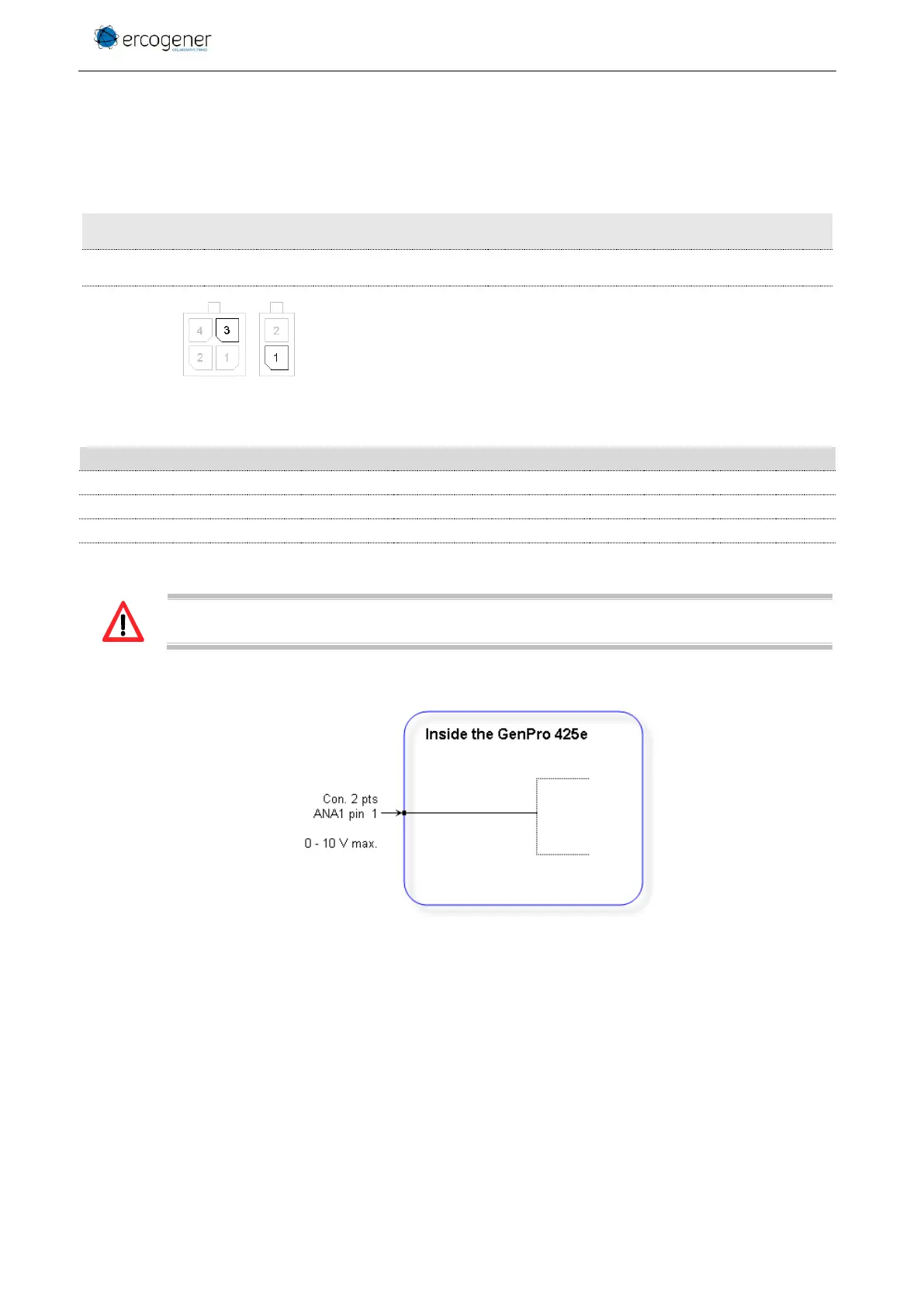
Table 30 : Characteristics of analog input 0-10V
The integrator has the responsibility to protect the input from electrical perturbations and to
respect the functioning parameters values.
Figure 17 : Internal electric scheme of analog input 0-10V