EG_GenPro425e_1103_UG_001_UK.docx
Descriptions and non-contractual illustrations in this document are given as an indication only.
ercogener reserves the right to make any modifications.
Dct_427_02
3.6.1.2 Direct connection
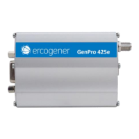
This method must be adapted depending on the diameter of wire used.
In the case of small-diameter wire (0.4mm²), the previous method is the most reliable.
After having prepared the wire, pinch it at more or less 12 mm from the end, and insert it in the connector.
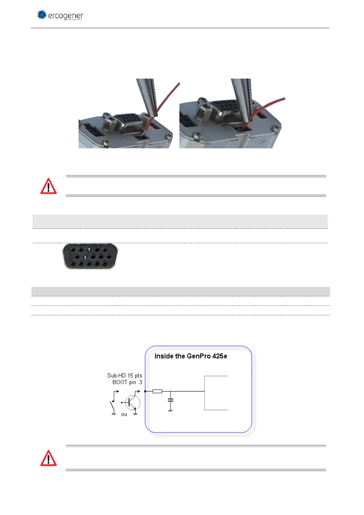
3.7 BOOT
This signal must NOT be connected, NOT used. The use of the BOOT function is strictly
reserved for the manufacturer and distributors.
Table 21 : Description of BOOT input
Table 22 : Conditions of use of BOOT signal
Internal Pull-Up Resistor
Figure 12 : Internal electrical scheme of BOOT
The use of the BOOT signal must be done through a transistor assembly or via dry contact.
The integrator has the responsibility to protect the input from electrical perturbations and to
respect the functioning parameters values.