EG_GenPro425e_1103_UG_001_UK.docx
Descriptions and non-contractual illustrations in this document are given as an indication only.
ercogener reserves the right to make any modifications.
Dct_427_02
3.9 Opto-coupled inputs
By default, the GenPro 425e provides 3 opto-coupled inputs E1, E2 and E3
As an option, it is possible to have
Analog input (0-10V)
Multi One Wire Input
These options cannot be installed simultaneously with the opto-coupled inputs.
3.9.1 Standard opto-coupled inputs
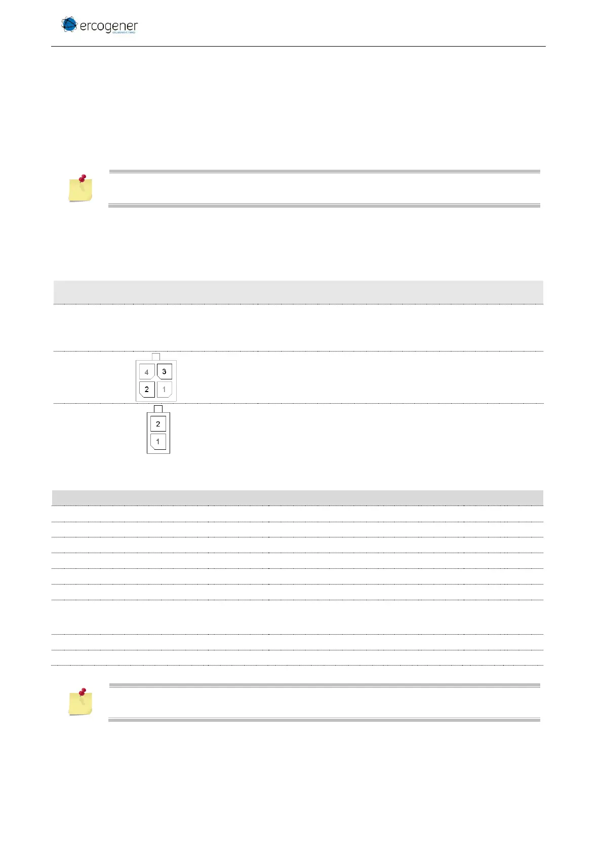
Table 25 : Description of opto-coupled inputs
2 Connector 4 pins
1 Connector 2 pins
2 Connector 2 pins
Corresponds to wires
2 – Orange or Yellow for E1
See ANNEX 1 - 4-pin Micro-FIT cable without fuse.
Corresponds to wires
1 - Yellow for E2
2 - Blue for E3
See ANNEX 2 - 2-pin Micro-FIT cable.
Table 26 : Characteristics of opto-coupled inputs
Saturation of transfer Ratio
If one or several input wires are not used, plug it (them) to GND (3)
.