EasyManua.ls Logo

Ercogener GenPro 425e - Digital Outputs

Ercogener GenPro 425e
51 pages
Print Icon
To Next Page IconTo Next Page
To Previous Page IconTo Previous Page
Loading...
EG_GenPro425e_1103_UG_001_UK.docx
Page 35 / 51
Descriptions and non-contractual illustrations in this document are given as an indication only.
ercogener reserves the right to make any modifications.
Dct_427_02
3.10 Digital outputs
Table 33 : Description of digital outputs
Signal
Connector 4 pts
Pins N°
I/O
Description
S1
1 Connector 4 pins
O
Open collector output
Corresponds to wires
1 Green or Brown for O1
See ANNEX 1 - 4-pin Micro-FIT cable without fuse
Table 34 : Characteristics of open collector output
Characteristics
Symbols
Conditions
Min.
Typ.
Max.
Unité
Max. voltage
V
CE0
Open transmitter
48
V
DC
Max. voltage
V
CES
V
BE
= 0 V
48
V
DC
Collector current
I
C
0.5
A
DC
Saturation voltage
V
CEsat
I
C
= 500 mA
1.3
V
DC
Dissipation
P
Ttot
T
amb
≤ 25 °C, T
j
= 110 °C
0.78
W
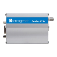
Figure 19 : Internal electrical scheme of the output
There is no protection. The user must respect the values of the above table (maximum
current and voltage).
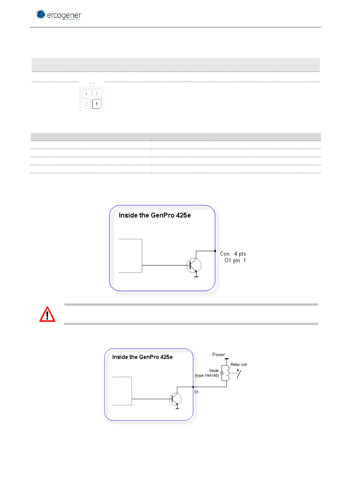
Figure 20 : Exemple de pilotage d'un relais

Table of Contents

Other manuals for Ercogener GenPro 425e

Related product manuals