EasyManua.ls Logo

ESAB EPP-360 User Manual

ESAB EPP-360
64 pages
To Next Page IconTo Next Page
Page #1 background imageLoading...
Page #1 background image
Valid for serial no. 015-xxx-xxxx0558 007 676 20110517
EPP-360
Instruction manual
Question and Answer IconNeed help?

Do you have a question about the ESAB EPP-360 and is the answer not in the manual?

ESAB EPP-360 Specifications

General IconGeneral
BrandESAB
ModelEPP-360
CategoryWelding System
LanguageEnglish

Summary

USER RESPONSIBILITY

SAFETY PRECAUTIONS - English

Essential safety guidelines for operating welding equipment to prevent injury or death.

PROTECT YOURSELF AND OTHERS

Measures to protect individuals from arc radiation, noise, burns, sparks, and hot metal.

FIRES AND EXPLOSIONS

ELECTRICAL SHOCK

Information on preventing severe injury or death from electrical shock during welding operations.

ELECTRIC AND MAGNETIC FIELDS

FUMES AND GASES

Precautions for preventing harm from welding fumes and gases, especially in confined spaces.

CYLINDER HANDLING

Procedures for safe handling of compressed gas cylinders to prevent rupture and injury.

EQUIPMENT MAINTENANCE

ADDITIONAL SAFETY INFORMATION

List of recommended publications for further safety information on welding.

MEANING OF SYMBOLS

Explanation of danger, warning, and caution symbols used in the manual.

INTRODUCTION

EPP-360 Features

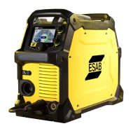
List of key features and specifications of the EPP-360 power source.

TECHNICAL DATA

General Installation Precautions

General safety warnings and compliance requirements for installation.

Placement

Input power connection

Instructions for connecting the EPP-360 to the primary power supply.

Input conductors

Input connection procedure

Step-by-step guide for connecting the input power conductors to the unit.

Output connections

Output cables (customer supplied)

Guidance on selecting and using appropriate output cables for the EPP-360.

Output connection procedure

Step-by-step instructions for connecting the output cables.

Parallel installation

Connections for Two EPP -360's in parallel

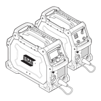
Detailed steps for connecting two EPP-360 units in parallel.

Parallel Operation Modes

Marking with two parallel EPP -360's

Instructions for using two parallel EPP-360 units for marking applications.

Interface cable connectors

CNC interface cables with mating power source connector and unterminated CNC interface

Pinouts and specifications for CNC interface cables with one unterminated end.

CNC interface cables with mating power source connectors at both ends

Water cooler interface cables with mating power source connectors at both ends

Pinouts and specifications for water cooler interface cables.

Power source parallel control cable

OPERATION

EPP-360 Block Diagram

Schematic representation of the EPP-360's internal components and their connections.

Control panel

Control Panel Components

Preset / Operate Switch

Selects cutting/marking mode and preset parameters.

Current Dial (Potentiometer)

Adjusts cutting current in panel mode (10-360 Amps).

Panel Remote Switch

Controls current control location (Panel or Remote/CNC).

Modes of operation

Single power source (used with the CNC, two basic modes of operation are possible)

Details on Panel Mode and Remote Mode for single power source operation.

Remote mode

Partial CNC Operation

CNC controls current reference and start/stop; micro computes initial parameters.

Remote with Full CNC Mode

CNC controls all parameters including pilot arc and slopes, using logic or analog inputs.

Multiple power sources

Sequence of operation

Step-by-step procedure for starting and performing plasma cutting operations.

MAINTENANCE

General

Critical safety warnings and requirements before performing any maintenance.

Cleaning

Instructions for cleaning the EPP-360 to ensure optimal performance and prevent overheating.

TROUBLESHOOTING

Troubleshooting guide

Steps to diagnose problems based on display indicators and initial power-up checks.

Help code list

Fault Isolation

Fans not working

Identifies possible causes and actions for fan malfunctions.

Torch will not fire

Diagnoses common issues preventing the torch from firing.

REPLACEMENT PARTS

General

Guidance on providing serial numbers when ordering parts.

Ordering

Instructions and recommendations for ordering replacement parts from ESAB.

REVISION HISTORY

Schematic diagram

Schematic Diagram (575V)

Wiring Diagram Details (J1, J7, J3, J4, J5)

Wiring Diagram Details (J1, J2, J3, J4)

Schematic Diagram (575V, CSA)

Wiring Diagram Details (J1, J3, J4, J5)

Wiring Diagram Details (J1, J3, J4, J7)

Wiring Diagram Details (J1, J2, J3, J4, J7)

BILL OF MATERIALS

Bill of Materials (Continued)

Bill of Materials and Component Locations

Bill of Materials and Label Locations

Component Location Diagrams

Component Location Diagrams (Continued)

Component Location Diagrams (Continued)

EPP-360 Dimensions

PCB Connection Diagrams

Input Power Box and PCB Connections

Resistor Assembly and Filter Network

Driver Board and Input Power Box Diagrams

PCB Connection Diagrams (Continued)

Main Transformer Diagram

Customer Service Contact Information

Related product manuals