14
E
Installing the Appliance
E1 Installation
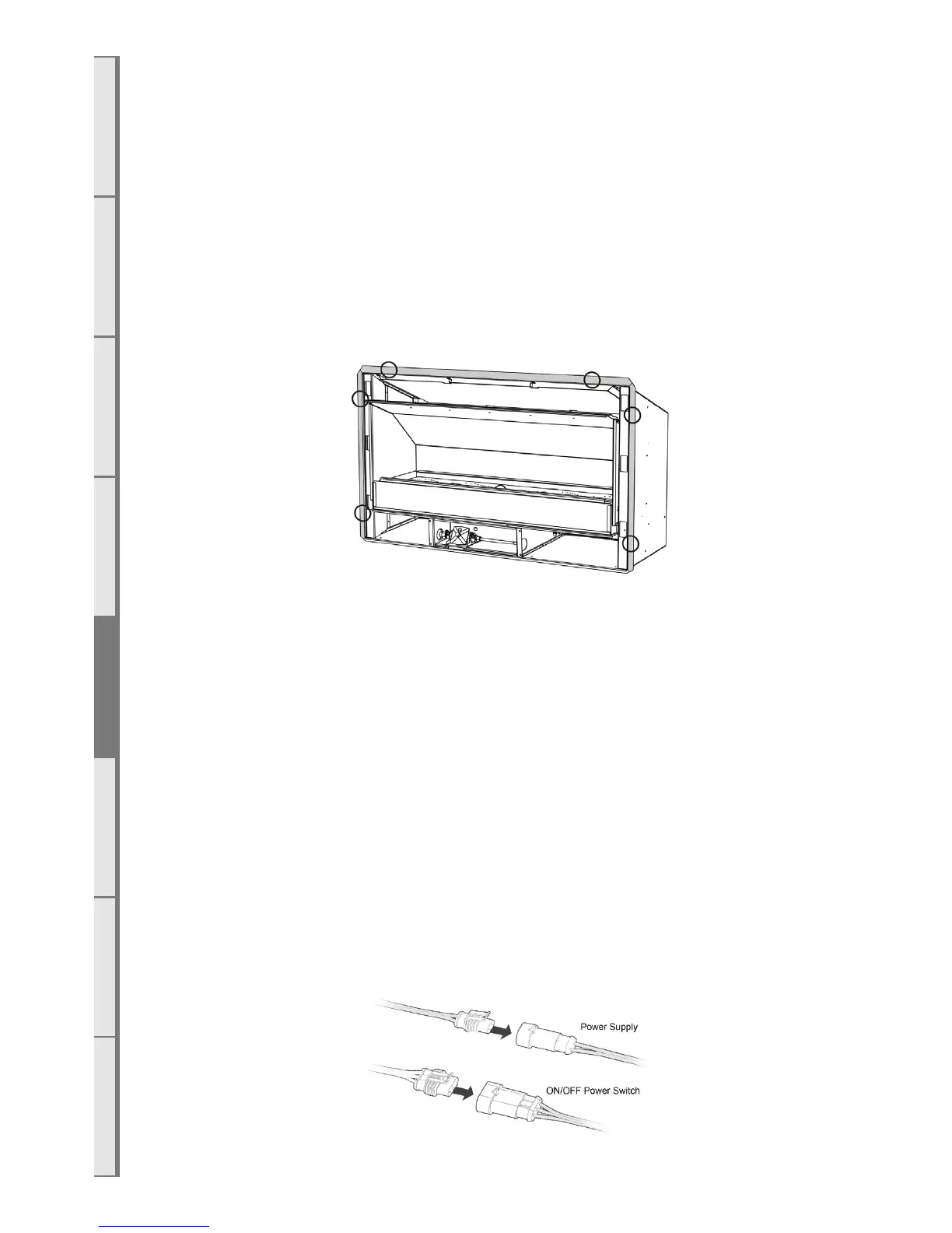
To fix the fire to the cavity, first drill 4 to 6 holes (5mm diameter) into the outer flange (shaded grey
in the image below). The holes should be evenly spaced around the flange and drilled in locations
which will provide the most support from the cavity framework behind the fire - suggested locations
are circled in the diagram below. Using the supplied stainless steel screws, fasten the fire to the cavity
through these drilled holes.
It is recommended that the outer flange is sealed to prevent water ingress into the cavity; high
temperature silicon may be used.
Ensure that the fire is secure and free from movement.
E2 Connecting the Gas Pipe
When the EF5000 has been pushed into position and secured, the flexible hose can be connected
to the inlet side of the appliance regulator at the front center of the fire. The hose and pipe assembly
should have been tested as per section D3 “Gas Pipe Position” on page 12.
No matter which connection the installer chooses, the regulator that is supplied in the fire MUST
NOT BE REMOVED. Removal of the regulator, or replacing it with one that is not intended for use
with an Escea EF5000, will void the limited appliance warranty.
The EF5000 must be disconnected from the gas supply piping system during any pressure testing of
that system at test pressures in excess of 3.5kPa (1/2 psi).
E3 Connecting the Power Supply and Power Switch
The power supply socket is located in the center line of the fire, below the firebox, facing the right
hand side behind the ignition tray. Push the 2 pin plugs together until they click.
The ON/OFF power switch socket plugs into the 3 pin plug lead situated at the front right hand side
of the fire. Push them together until they click.