Part 2 SES 2000 Vac (LS3) AUTOCLAVE
Page 10 of 53 ST-SM45g
PART 2 DESCRIPTION
10 When the door is closed, with the power switched on,
this is sensed by the control board via the door interlock
switch. If any attempt is made to open the door once the
cycle has begun, the display 'ERROR 2' will appear and
an audible signal will sound. Under these circumstances
it is necessary to switch the autoclave off, wait 5 seconds,
reset the error (see Part 3, para. 54) and restart the cycle.
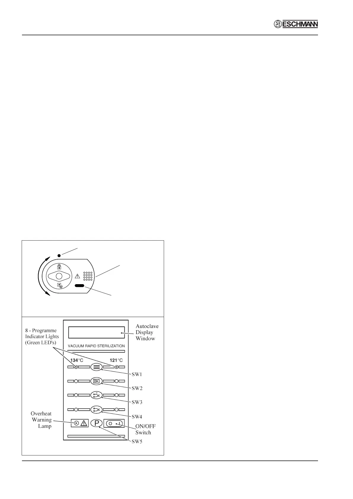
11 The autoclave operates automatically at the touch of
a single programme selector touch button ( Fig. 2.1b), and
has eight programmes:
❑ 134°C Porous load with drying (SW1)
❑ 134°C Wrapped load with drying (SW2)
❑ 134°C Unwrapped load with drying (SW3)
❑ 134°C Unwrapped load (SW4)
❑ 121°C Porous load with drying (SW1)
❑ 121°C Wrapped load with drying (SW2)
❑ 121°C Unwrapped load with drying (SW3)
❑ 121°C Unwrapped load (SW4)
12 Each programme selector button on the control panel
(Fig. 2.1b) will select either the 134°C or 121°C cycles.
The programme indicator lights, at each side of the
programme selector buttons, will change to indicate a
change of selection between 134°C and 121°C each time
the appropriate selector button is pressed. In addition,
the display will show the appropriate programme
description to confirm the programme that has been
selected. Once the programme and the temperature
range has been selected, the sterilization cycle will start
automatically, after a delay of approximately four seconds.
13 The printer, if fitted, will start printing and, as the
cycle progresses, various display messages will appear
in the display window to indicate the programme status.
Note: If a programme is started in error, it can be cancelled
by pressing the 'P' selector button (SW5), provided that the
cycle has not reached the water fill stage.
14 When a cycle is selected (SW1- SW4 pressed),
'CYCLE STARTED' will be displayed, quickly followed by
'VACUUM ON', indicating that the vacuum pump has
started, and the vacuum solenoid valve has opened to
evacuate the air from the chamber.
15 When the pressure in the chamber has decreased to
the required value for the programme selected, the water
fill valve will open and 'FILLING' will be displayed, indicating
that water is being sucked from the reservoir and into the
chamber.
16 When the cycle has started, the door cannot be
opened due to the electric door lock and vacuum force on
the door.
17 When the correct quantity of water has entered the
chamber, the water fill valve closes together with the
vacuum valve. The heater, controlled by the control
board, will switch on, and the pressure in the chamber will
increase. This phase is indicated by 'PULSING' being
shown on the display.
18 The heater is controlled by a system which ensures
that the operating temperature is reached with minimal
overshoot. Initially, the heater will be 'on' continuously
and the measured temperature will be displayed. Note,
however, that the system does not register temperatures
below 92°C.
19 Temperatures are displayed with a resolution of
0.1°C, using signal averaging to ensure a stable, accurate
display.
20 Control of the cycle is fully automatic with temperature
information being monitored by temperature sensors.
Timing is controlled by the control board and cycle times
cannot be adjusted. By comparing measured values with
known time/temperature relationships, the control board
is able to detect faults such as lack of water at the fill
stage, or loss of water and steam during the process, and
Fig. 2.1b Autoclave control panel
Fig. 2.1a Autoclave door handle
Locked
Unlocked
Safety catch
behind door plate
Door lock position
indicator
Chamber pressure
indicator