30
Connection
problemtorelay
board
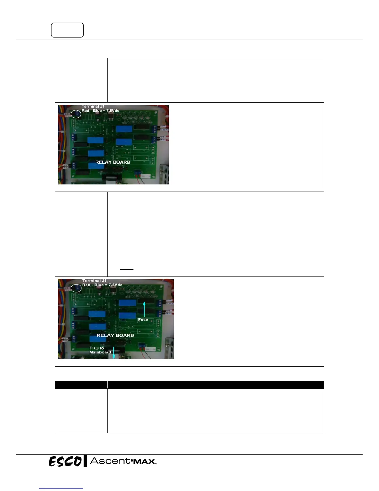
• SeeComponentLayouttolocatetherelayboard.
• MeasuretheincomingvoltageontheRelayBoardatterminalJ1(Notepolarity,
BLUEcableclosesttoedgeisnegative‐).SeeFigure1‐8.
• Voltageshouldbebetween6.75–8.25VDC.
• If
voltageisoutofrange,checkconnectionbetweenSMPSandrelayboard.
• Ifvoltageiscorrect,proceedtonextstep.
Defectiverelay
board
• Ensurethefollowingarecorrect:
o Mainboardisoperational
o FlatRibboncableisinstalledcorrectlytorelayboardandmainboardandshows
nophysicaldamage
o Relayboardhasthecorrectincomingvoltage(6.75–8.25VDC)
o Checkallfusesonrelayboard:Turn
offpower,removefusesandphysically
inspectorcheckcontinuity
o Allwiringconnectionsaregood
• Turnthecabineton.IftheFAN,LIGHT,SOCKETandcannotbecontrolled,replace
theRelayBoard.
NOTE:Whenreplacingrelayboard,pleasere‐connectallthecablesbackcorrectly.Anywrong
wiringmayresultindamage.
Problem2:Blowerdoesn’tfunction
Cause CorrectiveAction
FanisOff
• SwitchontheFanbypressingFanbuttononcontrolpanel.
• EntertheFanPINnumberifrequired(defaultis0001)
• TheLEDforFANshouldilluminateandtheFANshouldstart.
• IftheFANdoesnotoperate,proceedtonextstep.
• If
theLEDonthemembranedoesnotilluminate,checkconnectionfromcontrol
paneltomainboardandLCD,keypadmembrane.
Figure1‐8
Figure1‐9