27
8.2. PT100 CONNECTION
As it is possible to see on the connection diagram represented in Fig. 1 the controller foresees the mounting of
the PT100, 3 wire sensors.
Regarding the two poles PT100 it is necessary to short circuit the two terminals of the clamps marked
“C” with a clevis (fig.1) and connect the two wires of the PT100 between one of the above poles “C” and the
third pole which is still free; instead for the four wire one it is necessary to connect both wires to one of
the two pairs of twisted wires at the third pole and the other two wires of the other twisted pair to the two poles
marked “C”.
8.3. PRIMING OF THE PUMPS
To facilitate the priming of the pumps, it is possible to manually activate the output of the SETPOINT.
Such procedure is accessible even in presence of password by pressing simultaneously two keys (as following
described) while the visualization of the measure is in progress.
The procedure of priming of the pumps involves:
- Activation of the relay SETPOINT
- 4-20mA output is set to 20mA
- If in ON/OFF mode, TTL relay is activated; if in PROPORTIONAL mode, the TTL output is set to the maximum
frequency.
To effect such operation:
For the pump 1 press simultaneously the keys ▬ and ►. Until the keys stay pressed the whole outputs
remain activated.
For the pump 2 press simultaneously the keys + and ►. Until the keys stay pressed the whole outputs
remain activated.
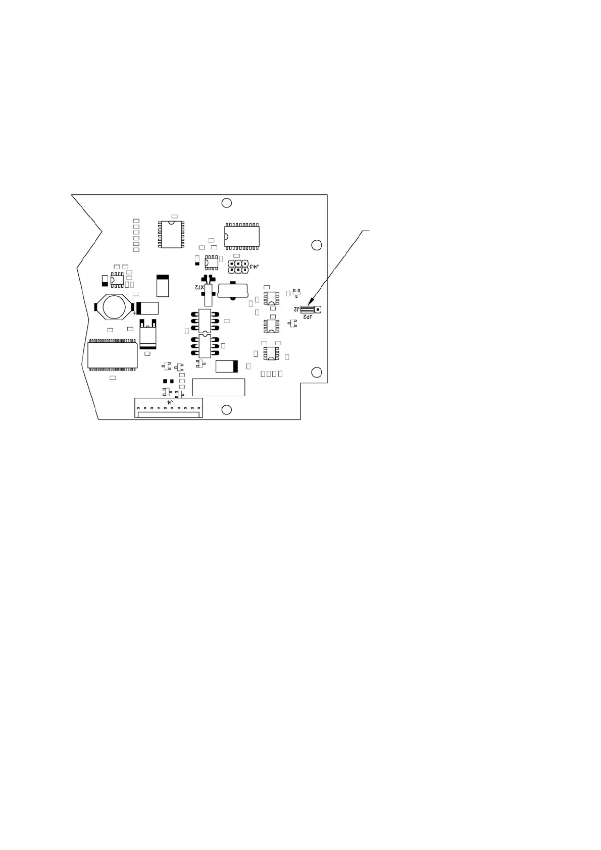
This jumper has to be positioned
as indicated to select PT100
temperature sensor