Planning 11
DMX Data Path
CAUTION: Data transmission will become unreliable if the DMX signal path
is not configured according to ANSI E1.11 - USITT DMX512(A).
CAUTION: ETC recommends laying out the DMX data path for your track
configuration BEFORE ordering all track and couplers to ensure that no loops,
T-junctions, or Y-taps are created that would disrupt data transmission.
Consider the following information when planning the DMXdata path:
• The DMX data line is only for low voltage with an approximate value of 50 V, 2 A
maximum.
• If X-couplers are required in your system, you must disconnect one or more data-line
connections to avoid data loops. See
Reconfiguring DMX Data Lines on page 22
.
• If L-couplers or T-couplers are required in your system, you may need to disconnect one
or more data-line connections to avoid data loops. See
Reconfiguring DMX Data Lines on
page 22
.
• When planning for the locations of end feeds, be aware that DMX and power cannot be
wired into the same end feed. Install separate end feeds for DMX and power.
• When planning for the locations of mid feeds, ETC recommends that you use mid feeds
to provide power to the track, not DMX. (Using a mid feed to provide data creates a T-
junction, which is disallowed.)
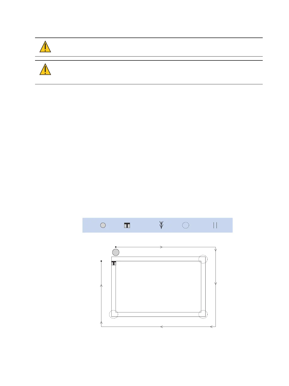
The following illustrations show examples of DMX data paths. These drawings are plan views,
showing the track system as if you were looking at it from above.
If you have additional DMX termination questions, please contact your local ETC
representative.
For more information on DMX, visit the ETC website: etcconnect.com/AboutDMX.
DMX IN
DMX
TERM
start
DMX
terminator
data
coupler
location
track
L-coupler
L-coupler
L-coupler
Key:
Figure 10: Simple DMX system