Planning 13
T-coupler
T-coupler
T-coupler
T-coupler
T-coupler
L-coupler
L-coupler
T-coupler
X-coupler X-coupler
L-coupler
L-coupler
X-coupler
D2
D3
D1
start
DMX
terminator
data
coupler
location
track
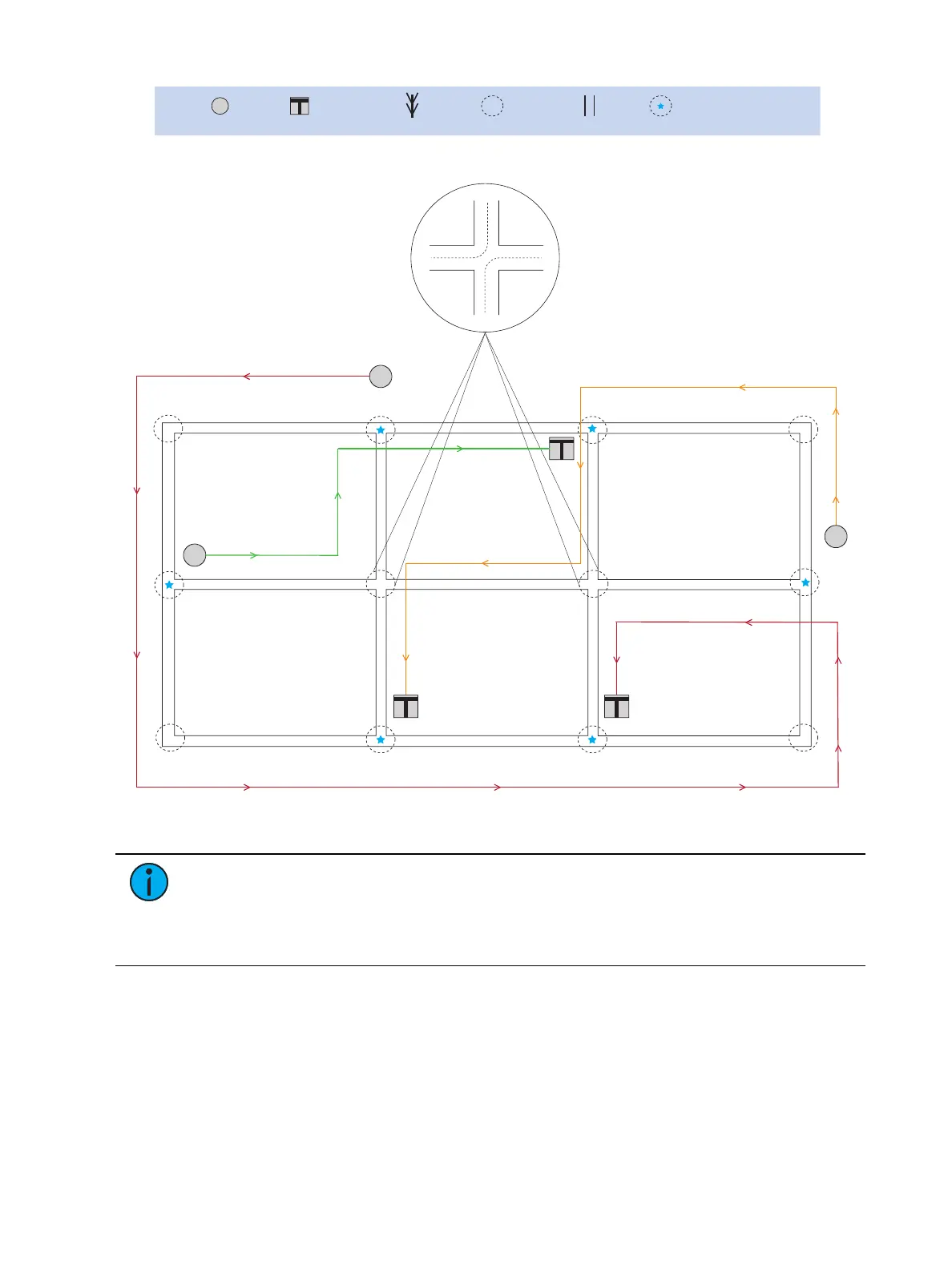
Key:
coupler wiring
requires modification
(see note below)
Figure 12: Complex DMX system
Note:
In the example above, individual DMX data lines would begin at the T-coupler
for D1 and at mid feeds for D2 and D3. Each data line (D1, D2, D3) would require
separate DMX terminators. You must disconnect some coupler wiring (in couplers
indicated with a star in the example above) for the data line to function as shown. See
Reconfiguring DMX Data Lines on page 22 for more information.