Euphonix System 5 Installation Guide System 5 Components
40
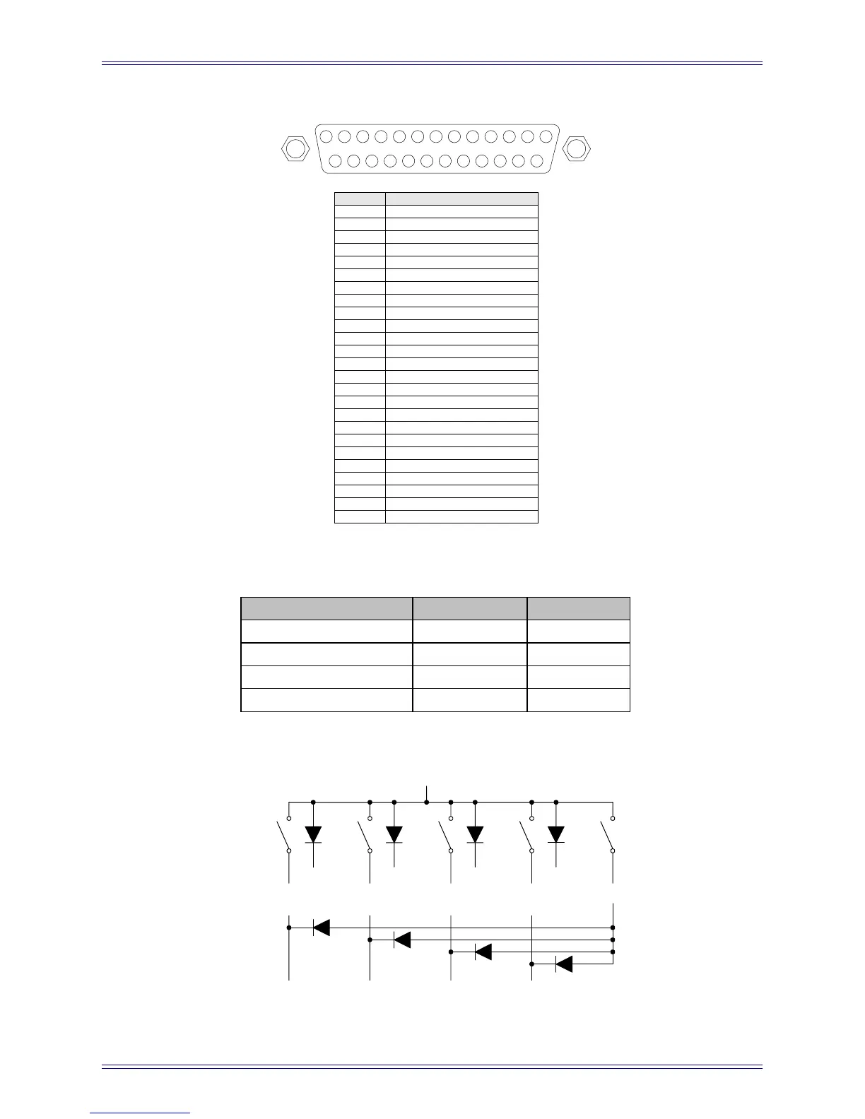
Figure 3-5 CM401 Expansion Port: DB-25 Female pinout
Table 3-1 Switch Functions
Figure 3-6 Typical Talkback Wiring
13
25
1
14
Pin #
1
2
3
4
5
6
7
8
9
10
11
12
13
14
15
16
17
18
19
20
21
22
23
24
25
Signal
LED 1 output (active low)
Switch 1 input (active high)
+5V
LED 3 output (active low)
Switch 3 input (active high)
+5V
LED 5 output (active low)
Switch 5 input (active high)
+5V
LED 7 output (active low)
Switch 7 input (active high)
+5V
+5V
+5V
LED 2 output (active low)
Switch 2 input (active high)
+5V
LED 4 output (active low)
Switch 4 input (active high)
+5V
LED 6 output (active low)
Switch 6 input (active high)
+5V
LED 8 output (active low)
Switch 8 input (active high)
Function
Talkback to Mon A (SLS)
Talkback to Mon B (Cue 1)
Talkback to Mon C (Cue 2)
Talkback to Mon D (Cue 3)
Switch
Switch 1 (pin 2)
Switch 2 (pin 16)
Switch 3 (pin 5)
Switch 4 (pin 19)
Tally
LED 1 (pin 1)
LED 2 (pin 15)
LED 3 (pin 4)
LED 4 (pin 18)
+5 V (pins 3, 6, 14, 17)
Pin 2
TB to MON A
(SLS)
TB to MON B
(CUE 1)
TB to MON C
(CUE 2)
Pin 1
Pin 16
Pin 15
TB to MON D
(CUE 3)
Pin 5
Pin 4
Pin 19
Pin 18