Euphonix System 5 Installation Guide System 5 Components
51
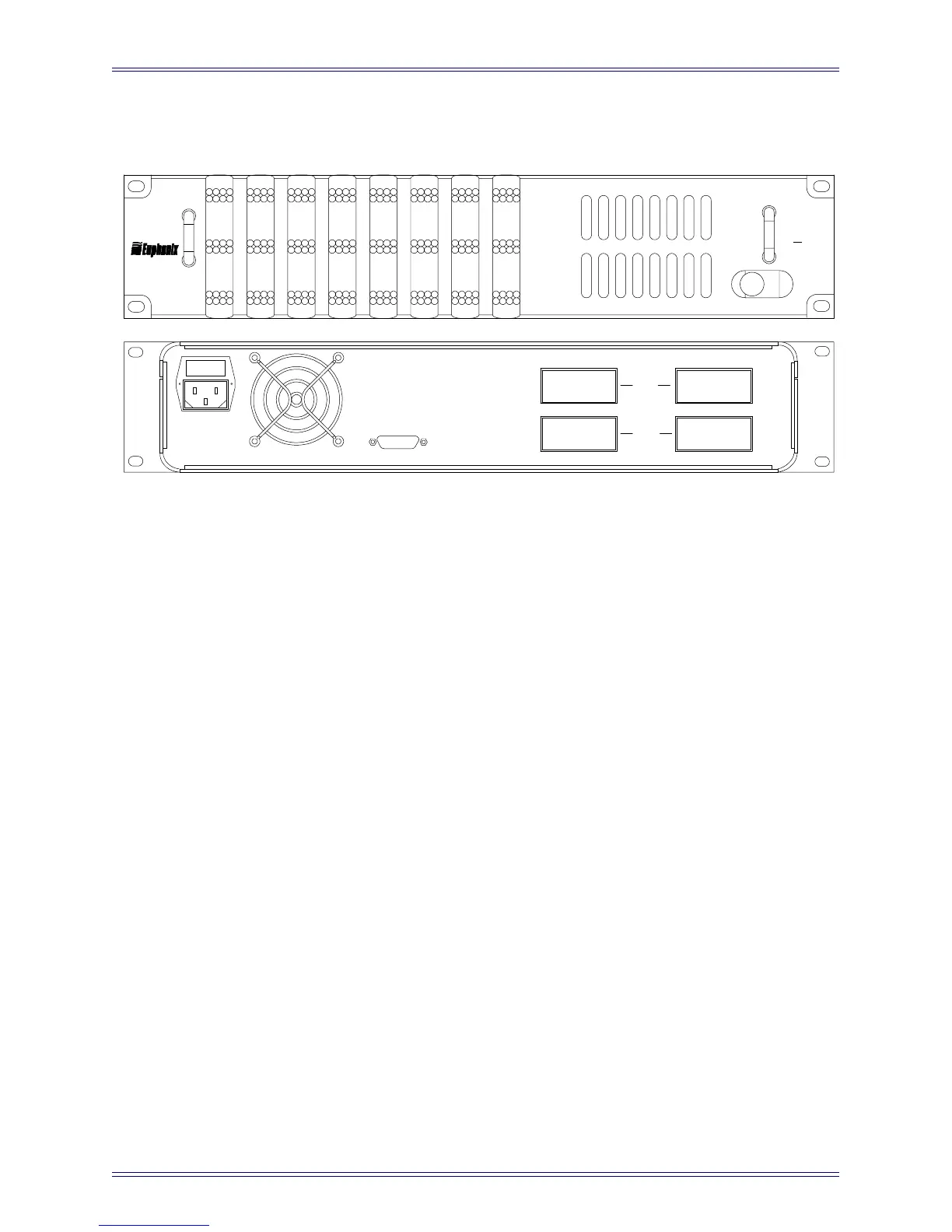
ML530 Mic/Line Interface
Figure 3-15 ML530 Front and Rear Panels
Inputs (two 38-pin ELCO sockets): A total of 24 microphone inputs are received on two
38-pin ELCO connectors (connectors and pins provided).
Outputs (two 38-pin ELCO sockets): A total of 24 outputs are provided on two 38-pin
ELCO connectors. These outputs feed an AM713 Analog to MADI Converter (a 24 male
XLR to 38-pin ELCO cable is provided).
Control (DA-15): Connect to the System
Computer via TCC breakout cable (provided).
All patching, switching and gain controls are communicated via this connection.
AC Line In (IEC) and Fuse Tray: Accepts standard IEC power cord (provided). An
autoranging switching supply accepts voltages between 90–250 VAC, 50–60 Hz.
ML
530
1
9
17
2
10
18
3
11
19
4
12
20
5
13
21
6
14
22
7
15
23
8
16
24

 Loading...


